IME there are no active filters that will work for this. I was able to do pretty well with passive L/C at 600 Ohms a long time ago, built with air coils and all wood forms (myrtle was not necessary). IIRC this was proposed many years ago by one of the British designers.
I seriously doubt a wide range general purpose generator can be made with any of these techniques.
I seriously doubt a wide range general purpose generator can be made with any of these techniques.
Last edited:
Why??
I'm having a little bit of trouble understanding the motivation for designing a very low distortion digital oscillator, especially when it appears to need so much analog stuff after it to achieve the very low distortion levels that are desired.
Yes, it would be cool to be all-digital, but the discussion here has been mostly about adding analog circuitry to get the distortion down, so we are sort of back to where we started.
Perhaps it is the dead-nuts-on accuracy of the frequency?
If so, build a very low distortion analog state variable oscillator and phase lock it to a digital oscillator. Yes, the center frequency of the analog oscillator would have to be brought within the lock range of the PLL first, but that is really not a bigger deal than what we have to do in a THD analyser. In fact, the auto-tuning in a conventional THD analyzer is already essentially a phase locked loop, just without having the phase locked in most cases.
So, what am I missing in terms of motivation for this digital, low-distortion design exercise?
Cheers,
Bob
Perhaps it is the dead-nuts-on accuracy of the frequency?
This is useful for using synchronous FFT techniques. I have long ago given up trying to understand measuring distortion in the presence of the fundamental at these levels. It opens up the door to numerous confounding effects.
I'm having a little bit of trouble understanding the motivation for designing a very low distortion digital oscillator, especially when it appears to need so much analog stuff after it to achieve the very low distortion levels that are desired.
Yes, it would be cool to be all-digital, but the discussion here has been mostly about adding analog circuitry to get the distortion down, so we are sort of back to where we started.
Perhaps it is the dead-nuts-on accuracy of the frequency?
If so, build a very low distortion analog state variable oscillator and phase lock it to a digital oscillator. Yes, the center frequency of the analog oscillator would have to be brought within the lock range of the PLL first, but that is really not a bigger deal than what we have to do in a THD analyser. In fact, the auto-tuning in a conventional THD analyzer is already essentially a phase locked loop, just without having the phase locked in most cases.
So, what am I missing in terms of motivation for this digital, low-distortion design exercise?
Cheers,
Bob
It can be pretty much all digital. The lock in amplifiers can actually be digital. The reason to build such an oscillator is to test A/D converters!
It is that calibration cycle thing. How can I make a more precise unit from a group of lesser precision ones? Reciprocity and averaging are the two techniques that come to mind. In this case it is parse with reiprocity.
A few years ago I've posted in this thread about the passive notch filter I'm using to measure very low distortion. Recently the interest for this design seems to have grown which triggered me to upload the files onto my webpage:
Analog Circuit Design · Samuel Groner · Resources · Low Distortion Oscillators
There's currently a group buy for PCBs running, see: www.diyaudio.com/forums/group-buys/...ners-low-distortion-passive-notch-filter.html.
Samuel
Analog Circuit Design · Samuel Groner · Resources · Low Distortion Oscillators
There's currently a group buy for PCBs running, see: www.diyaudio.com/forums/group-buys/...ners-low-distortion-passive-notch-filter.html.
Samuel
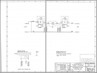
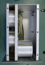
Here is an example of a passive low pass filter. In simulation, it gets down to -130 dB at HD3. At HD2 its -80dB. Photos of the physical implementation are included. This is for 10 KHz. The core for the inductors seems to be something like Delrin.
It could be scaled to 1 KHz. Below that would probably be pretty crazy.
It could be scaled to 1 KHz. Below that would probably be pretty crazy.
Attachments


It could be scaled to 1 KHz. Below that would probably be pretty crazy.
That looks good you could run a really good DAC at 15K through that and get 70+dB at all harmonics, again how do you verify it? The 1K version was a pain I used 100's of feet of #18 copper wire, the Q was not as good as that but I managed -40dB over the SoundTech 1700 (~-106dB).
Ed - I don't have anything anymore but an old EG&G app note on the PAR lock-in amps. They don't really cover how well you can do in the presence of a large signal but there is this...
The signal-channel notch mode (predetection filter) is used to attenuate the fundamental by nearly 80 dB. This reduces the likelihood of mixer overload as the sensitivity is increased. An oscilloscope connected to the monitor output connector (premixer) helps adjust the notch for maximum effectiveness.
Do you have some pictures of say at 2V rms in?
Last edited:
Do you mean without fundamental suppression? Direct measurement with FFT?This is useful for using synchronous FFT techniques. I have long ago given up trying to understand measuring distortion in the presence of the fundamental at these levels. It opens up the door to numerous confounding effects.
Low Pass Filters Freq
Demian, that is pretty impressive and it is fairly large in physical size.
Precluding it's use in a small enclosure?
Enclosure:
So now I have this image in my head of something like a fairly large fully enclosed amplifier, Standard rack-mount width with 13inch to 17inch depth and something like 5 or 6 rack-mount sections high.
That is, a fully enclosed isolated oscillator, fed through the filter(s)
to the output. Heck why stop there? Make this a fully enclosed and
shielded rack too, multiple layers of shielding.
Also have room at the top for easy placement of the
DUT, close the hatch, pull a few Bar and off we go.
Commentary:
Yeah, I got carried away.
For those following along, my links were not to state this is what
we must do and use, rather it is what I've found and if the idea is
valid what a the best devices and components to use.
Question:
What is the FREQ range we are considering for the low pass filter?
Is it fixed? Or can we use a few different points to get us there?
LOW PASS FILTERS
Shibasoku 725D:
20KHz
30KHz
100KHZ
HP339A:
30KHz
80KHz
Sound Technology 1700b:
80KHz
Amber 3501A:
30KHz
80KHz
National Panasonic VP7722A:
30KHz
80KHZ
Any others we need to know about?
Here is an example of a passive low pass filter. In simulation, it gets down to -130 dB at HD3. At HD2 its -80dB. Photos of the physical implementation are included. This is for 10 KHz. The core for the inductors seems to be something like Delrin.
It could be scaled to 1 KHz. Below that would probably be pretty crazy.
Demian, that is pretty impressive and it is fairly large in physical size.
Precluding it's use in a small enclosure?
Enclosure:
So now I have this image in my head of something like a fairly large fully enclosed amplifier, Standard rack-mount width with 13inch to 17inch depth and something like 5 or 6 rack-mount sections high.
That is, a fully enclosed isolated oscillator, fed through the filter(s)
to the output. Heck why stop there? Make this a fully enclosed and
shielded rack too, multiple layers of shielding.
Also have room at the top for easy placement of the
DUT, close the hatch, pull a few Bar and off we go.
Commentary:
Yeah, I got carried away.
For those following along, my links were not to state this is what
we must do and use, rather it is what I've found and if the idea is
valid what a the best devices and components to use.
Question:
What is the FREQ range we are considering for the low pass filter?
Is it fixed? Or can we use a few different points to get us there?
LOW PASS FILTERS
Shibasoku 725D:
20KHz
30KHz
100KHZ
HP339A:
30KHz
80KHz
Sound Technology 1700b:
80KHz
Amber 3501A:
30KHz
80KHz
National Panasonic VP7722A:
30KHz
80KHZ
Any others we need to know about?
Sync these filters set the band width of the analyzer. I think what Richard is suggesting is filter to suppress the 2nd, 3d harmonic and up. So the question is what test frequencies will be used.
What about an elliptic response filter. I seem to recall Samuel saying that in theory an elliptic filter can completely remove the second harmonic.
Of course that was for use as an oscillator.
What about an elliptic response filter. I seem to recall Samuel saying that in theory an elliptic filter can completely remove the second harmonic.
Of course that was for use as an oscillator.
Last edited:
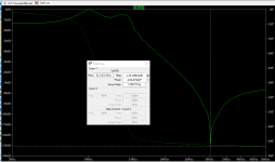
The simulations I am working on are elliptic filters, where a zero can be placed at either the 2nd or the 3rd harmonic - or somewhere in-between. The 3rd harmonic is typically the highest for the AK4490, so that is probably where I will start.
In the simulations the 3rd harmonic (3 kHz) is attenuated by around 48 dB. The 2nd harmonic is only attenuated by 14 dB in this case.
The filter is a 3rd order filter.
Higher harmonics are attenuated by at least 30 dB.
A schematic/layout is in progress, but it will be a while before I get a chance to test it.
Demian, that is pretty impressive and it is fairly large in physical size.
Precluding it's use in a small enclosure?
So now I have this image in my head of something like a fairly large fully enclosed amplifier, Standard rack-mount width with 13inch to 17inch depth and something like 5 or 6 rack-mount sections high.
That is, a fully enclosed isolated oscillator, fed through the filter(s)
to the output. Heck why stop there? Make this a fully enclosed and
shielded rack too, multiple layers of shielding.
Yeah, I got carried away.
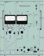
Per your request- The CLT-1:
Double shielded 19" W X 24" H X 12" D (for something made in a Metric country it surprised me that the dimensions are exact inch). It also weighs about 40 Lb of all aluminum construction. The case is two layers. The output is transformer coupled for all ranges except the center one.
Per Scott's note, how do you verify the performance? At -160 even metal film resistors can exhibit some distortion. Actually, at those levels it's more of a modulation effect from the signal than a material nonlinearity. However, everything will start to show some impact at those levels. You really cannot seperate the source from the analysis.
Per Ed's comment on testing ADC's; for a modest price, you can get Victor's oscillators which are substantially better than any ADC I have ever seen a datasheet for. I have not pursued injection locking of one yet. My earlier efforts on the similar KH4400 did not work so well but I'm up for trying again.
The Boonton 1120 has a PLL locked oscillator. Most of the smarts are done in a Z80 but it is synthesizer accuracy in an analog state variable oscillator with really good flatness. Its performance is limited by the analog multipliers and Jfet attenuators.
Attachments
Do you mean without fundamental suppression? Direct measurement with FFT?
Not necessarily, synchronous techniques allow optimum windowless averaging, having the fundamental and all harmonics in exact bins makes it work.
IMO he best bet on an A/D test would be to scale the CLT filter to your desired frequency and filter the output of a really good DAC and record many averages. Problems that remain, many systems are only at their best in differential mode and A/D's can be fussy about source impedance vs frequency.
Demian is right there are no A/D's that challenge the best implementations of the op-amp oscillators that anyone can buy or build.
Demian is right there are no A/D's that challenge the best implementations of the op-amp oscillators that anyone can buy or build.
Yes. At that time we thought it was another option and i was going to bring it up again. That you went ahead and designed a passive one is really great.A few years ago I've posted in this thread about the passive notch filter I'm using to measure very low distortion. Recently the interest for this design seems to have grown which triggered me to upload the files onto my webpage:
Analog Circuit Design · Samuel Groner · Resources · Low Distortion Oscillators
There's currently a group buy for PCBs running, see: www.diyaudio.com/forums/group-buys/...ners-low-distortion-passive-notch-filter.html.
Samuel
I have several of Victors osc/gen. They did not do as well as davada's. maybe Victor has tweeked a few to get it lower... dont know. Anyway, at -145 we only need another 15-20dB atten of harmonics to get us into the -160 and nothing much in existance can measure lower than that for any amount of money. But for lesser osc/gen readily available (Krone-Hite etc) more is needed. So, 20-30db rejection is something to shoot for.
Thx - RNMarsh
Last edited:
Scott all A/Ds or is it more or less with different types? SD, SAR ect.
It does depend but many data sheets have information, unfortunately most of the audio converters today are only pitched to a few huge customers who get personal service.
There is one significant problem with Victor's oscillators, he doesn't put them in a large fancy box and charge enough for them to get the proper respect.
Demian,
There actually are very high resolution A/D converters used for things like scales. Heresy but not all applications are audio.
Demian,
There actually are very high resolution A/D converters used for things like scales. Heresy but not all applications are audio.
There is one significant problem with Victor's oscillators, he doesn't put them in a large fancy box and charge enough for them to get the proper respect.
It actually is an impediment. I was the person who 'discovered' Victor several pages down on the Google search... looking for low distortion gen. I told people at DIYAudio. I have several at different freqs. But I have not put them in a box with PS and I/O etc. A box was made by a DIYer to hold several... but who has the time?
The fixed freq was a problem for me and having a bunch of Victors to cover the range wasnt my cup of tea. A variable freq gen of ULD was needed. Davada took up the challenge and he did a great job.... low thd/thd+n at any freq and level. AND, I could buy one from him built and in a chassis. He deserves a medal. No switched filter elements and knobs. Some one should make it commercially available... sell it to KH or HP , TEK or Boonton, Fluke or R&S etc.
If a LP or notch can make it better, i will apply it to anyone's gen. A variable freq notch or LP that is sync'ed to the gen/osc freq would be nice.
THx-RNMarsh
Last edited:
There actually are very high resolution A/D converters used for things like scales. Heresy but not all applications are audio.
And they are not tested like audio converters. Mettler switched to force balance for their 6+ digit scales decades ago at the time the I never saw anything but quasi-DC tests, no idea how far up in BW they have gone.
- Home
- Design & Build
- Equipment & Tools
- Low-distortion Audio-range Oscillator