I was thinking about those with the 24 bits of real resolution. However 100 samples per second is not too interesting for audio. Even the Keysight 3458 with its 8 1/2 digit resolution and 100K sample per second doesn't get both at the same time.
if you need to verify one of those real 24 bit ADC's you need a 7 dial KV divider or a JJ array.
However for verifying linearity of AC response you could use a clean sine wave and a ratio transformer.
if you need to verify one of those real 24 bit ADC's you need a 7 dial KV divider or a JJ array.
However for verifying linearity of AC response you could use a clean sine wave and a ratio transformer.
... but who has the time?
THx-RNMarsh
I thought this was DIY? Here's one close to -150dB (fiddling with passives probably can improve it) all with off the shelf parts. Why make this thread for an audience of 2 or 3 people?
http://www.janascard.cz/PDF/An ultra low distortion oscillator with THD below -140 dB.pdf
Last edited:
The Januscard documentation looks better than when I first saw.it. Getting that performance with an optocoupler is great. They are easier to use.
I believe Victor's boards have been improved over the first gen as well.
I believe Victor's boards have been improved over the first gen as well.
Time is a flying.I built an oscillator based on that design. I changed it to 1 kHz. The performance is very good.
It is described here
with pictures a few posts later.
I just noticed that is was more than 5 years ago!
I have found opto couplers have temperature issues and in my best oscillator I do control the temperature with a peltier device. I also go for lower impedance and use parallel op amps. As mentioned before I use two stages of Wien bridges, one is the oscillator the other a filter.
The trickiest part is the voltage detector and feedback regulator. If you monitor that stages output you may see oscillation at a very low frequency.
Even with voltage regulated and filtered batteries still not at. -160 dB or so I think.
The trickiest part is the voltage detector and feedback regulator. If you monitor that stages output you may see oscillation at a very low frequency.
Even with voltage regulated and filtered batteries still not at. -160 dB or so I think.
Even with voltage regulated and filtered batteries still not at. -160 dB or so I think.
Ed, have you read B. Oliver's paper on the HP oscillator? He goes into the maths that shows the distortion can never be zero or the amplitude would never stabilize on these types of oscillators. That's why some folks have problems with the LT oscillator. The composite amps have so little distortion when you try to tweek it it tends to wander off. Jim Williams sent me a lot of literature on this after I called him on the "distortionless" claim.
According my own measurements all the 1kHz boards, that was built within last year or little more, have the harmonics lower than -150dB at full output 2,8V RMS. Typical harmonic levels are around -155dB, but some boards may go to -160dB. Also I observed the artifact when the boards often may have significantly lower 3H, when the opamp output is under the load around the 1 kohm.
From the first time, all my measurements was done via the passive twin T notch. Now I am using 1kHz twin T built from the selected polystyrenes from RCL components and the metal film resistors of course. As I previously wrote, every capacitor must be tested before using for the ULD measurement purposes,, because the some examples may distort relatively high. Only statistics, logic and step by step implementation can help in this way.
Typical problem for my customers is to get proper ULD measurements, because they do not use or do not have passive twin T filters with the tested performance.
Little about the other things. This box perfectly fits for the one oscillator board:
1pcs White Electrical Instruments Aluminum Box 100*65*35mm DIY | eBay
Needs only to drill the face panel holes.
The regulator for 35VDC also can be easy found:
LM317 DC Linear Voltage Regulator Step down Power Supply Module 5V 6V 9V 12V 24V | eBay
Easiest and cheapest way is to use small 2W transformer with 15VAC output and rectifier-voltage doubler for to power the LM317 regulator. The adapter type supply is preferred, when the transformer is far from the oscillator board.
All this is relatively cheap and for DIYers.
Finished solution include twin T probably is possible, but will be not so cheap.
Victor.
For oscillators having less distortion than this, more sophisticated AVC methods are probably desirable. ”Bernard M. Oliver".
And they are not tested like audio converters. Mettler switched to force balance for their 6+ digit scales decades ago at the time the I never saw anything but quasi-DC tests, no idea how far up in BW they have gone.
The ones we have at work are extremely slow to respond, so probably not too high. How much of that is on the mechanical side, however, I don't know.
Victor -- impressive performance you're getting!
According my own measurements all the 1kHz boards, that was built within last year or little more, have the harmonics lower than -150dB at full output 2,8V RMS.
Finished solution include twin T probably is possible, but will be not so cheap.
Victor.
Victor. Nice work and i need to get your newer designs now. Please go ahead and make some with the added twin-T. I'm not on a tight budget so maybe just make 2-3 for me and tell me what you want for it.
Thank you,
Richard
Scott,
Yes. The second resonator can easily drop 40 dB of the oscillators distortion.
One trick is to use better than a simple filter in the level set.
The limiting issue may be the distortion inherent in passives!
Things like capacitor mounting vs vibration axis actually show up.
Victor seems to be getting good results with simpler final product, but that hides the effort that has to go into tweaking and qualifying everything.
Last edited:
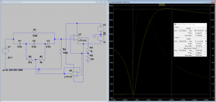
20 dB low Q notch to go in front of an analyser
Off and on for years I have been looking for a low Q notch I could put in front of a conventional analyzer to increase its sensitivity. The problem with the passive notches (and the active ones) is that the fundamental is essentially removed leaving nothing for the analyzer to work with. If you try to lower the Q usually HD2 is attenuated and the usable passband (+/- 1 dB) is still quite narrow.
The link to the Hall filter writeup PCB for Samuel Groner's low distortion passive notch filter suggested a way through this and at least in simulation it works well. With 20 dB of fundamental attenuation the harmonics from the opamps should not be an issue except for the ultra oscillators discussed here lately. HD2 up is within 2 dB so the instrument will read correctly. Scaling by 20 dB or one order of magnitude is easy to manage.
The low Q means that the fundamental can be between 960 Hz and 1060 Hz without significant compromise in measurement accuracy (+/- 1 dB).
This is different from Bob Cordell's distortion magnifier since this is targeted at sources and extending the performance of conventional analyzers. On paper you can take an instrument with a -100 dB floor to -120 dB. However noise etc. will probably limit the performance.
I have been way too busy to build anything for ages. Maybe I can get a local HS student to give it a try with this but most are more interested in coding and the like.
Attachments
The problem with the passive notches (and the active ones) is that the fundamental is essentially removed leaving nothing for the analyzer to work with.
I have been thinking to use Jan Didden's Autoranger and take the balanced output to a soundcard and the unbalanced output to Samuel Groner's notch filter + a post amp and take that to a second input to the soundcard. That way we still have the fundamental available to the software analyser.
Any thoughts on the idea?
Hochopeper:
It's an excellent solution if you are up to the software challenges. A quick workaround is to overlay the two channels but you still have some issues with scaling and reading the results. Software to make sense of the two channels would be better but not simple.
It's an excellent solution if you are up to the software challenges. A quick workaround is to overlay the two channels but you still have some issues with scaling and reading the results. Software to make sense of the two channels would be better but not simple.
maybe if an inverted version of a high Q notch filter was blended/combined with the non-inverted notch, we can have narrow (high Q) without high attenuation at the notch freq??
Thus controlling the notch depth.
-RNM
Thus controlling the notch depth.
-RNM
Last edited:
Victor. Nice work and i need to get your newer designs now. Please go ahead and make some with the added twin-T. I'm not on a tight budget so maybe just make 2-3 for me and tell me what you want for it.
Thank you,
Richard
Thank you, Richard. Now is the hot summer in our country, and I am relaxing. Maybe in September we can talk about the business more. The complete ULD measurement system must be very well designed in the accordance with the all devices and the conditions what will be used.
Victor.
I tried this but there is pole canceling effect even with active component buffering. Lower Q is easier to achieve with LCR because the damping is already naturally there. I think we need to dig into more advance filter books and or software..maybe if an inverted version of a high Q notch filter was blended/combined with the non-inverted notch, we can have narrow (high Q) without high attenuation at the notch freq??
Thus controlling the notch depth.
-RNM
I have some.
Before the op amp really took off in pro audio equalizers were done with what was referred to as simply choke and cap with an output amplifier to make up for insertion loss. The inductors were not insanely large. large.
Even into the 80s some guys preferred them to the so called active equalizers.
They actually did sound better.
- Home
- Design & Build
- Equipment & Tools
- Low-distortion Audio-range Oscillator