Viktor, I also had some cable issues that I solved and now I am at the measurement limit of my AP SYS2722 which is about -120dB.
I have designed a tracking 40dB notch for use with the autoranger MK II and the next step is to run your oscillator through the notch and see what comes out.
There is indeed some mains poles so another improvement will be to install a SilentSwitcher. No mains and low noise, that should also help.
So, the ball is in my court firmly ;-). Will report here of my findings.
Jan
Jan; What is the capacitance between the input supply and the output? When you are working at -120 dB+ it takes very little leakage to show up.
I fired them up today, but the performance is not good, barely make -100dB.
Jan
It's look that OPAMP in the input buffer of the sound card has failed.
Show the noise floor without a signal at the input
It's look that OPAMP in the input buffer of the sound card has failed.
Show the noise floor without a signal at the input
Uhhh there is no soundcard in the system, so your clearvoyance failed ;-)
Jan
Jan; What is the capacitance between the input supply and the output? When you are working at -120 dB+ it takes very little leakage to show up.
Yes, redressing cabling helped; it is less now but will go away completely once I install the SilentSwitcher.
In the mean time I am reaching the basic performance of the SYS2722.
Can you and anyone reading this please comment on the following reasoning:
Assume I have an oscillator with -130dB distortion. I have an analyzer with -110dB performance.
I also have a 40dB notch at the test frequency; assume the notch is distortion free.
So I send a nominal 0dBV oscillator signal with -130dBV distortion through the 40dB notch. What comes out is a signal at -40dBV level and -130dBV distortion.
The analyzer ranges up 40dB and then has a signal at 0dBV with -90dBV distortion.
This -90dBV distortion is clearly shown in the analyzer as it is above its base level. So I read off -90dBV and add 40dB and conclude the original signal had -130dBV distortion.
With the distortionless 40dB notch I can now measure -110dB - 40dB = -150dBV distortion.
Correct?
Jan
Last edited:
The 35V supply feeds the requirements.
[snip]
If you wish, I can offer to send me the boards for testing and repairing. Also if your boards are very old, I can make the possible improvements for them. Otherwise any questions please.
Victor
Victor, my SilentSwitcher provides +/-15V, extremely low noise, I assume I could connect that directly to the board?
I noticed also that the output voltage of the 1kHz generator 'breathes', slowly growing and going down again. Not sure what's going on.
I will first update the supply, when that doesn't fix it I may take you up on the offer to check it out.
Jan
You will get som inaccuracy when you approach the -150dB. When the distortion from the oscillator + notch filter is around the same level as the distortion from your analyzer, you may have constructive or destructive addition of the signal, depending on the phase of the distortion signals.With the distortionless 40dB notch I can now measure -110dB - 40dB = -150dBV distortion.
Correct?
Does the analyser functions equally well at 0dB and +40dB gain ?
Patrick
Almost, there may be a few dB difference, but for this case study we can assume the same.
Jan
You will get some inaccuracy when you approach the -150dB. When the distortion from the oscillator + notch filter is around the same level as the distortion from your analyzer, you may have constructive or destructive addition of the signal, depending on the phase of the distortion signals.
Jens, OK, yes, understood.
Jan
Victor, can I just connect the new +/-15 to appropriate points for the opamps, and leave the TL431 stuff as it is, or will that cause problems?
Have you published a schematic and board layout, I can't find it online.
Jan
Have you published a schematic and board layout, I can't find it online.
Jan
Yes, redressing cabling helped; it is less now but will go away completely once I install the SilentSwitcher.
In the mean time I am reaching the basic performance of the SYS2722.
Can you and anyone reading this please comment on the following reasoning:
Assume I have an oscillator with -130dB distortion. I have an analyzer with -110dB performance.
I also have a 40dB notch at the test frequency; assume the notch is distortion free.
So I send a nominal 0dBV oscillator signal with -130dBV distortion through the 40dB notch. What comes out is a signal at -40dBV level and -130dBV distortion.
The analyzer ranges up 40dB and then has a signal at 0dBV with -90dBV distortion.
This -90dBV distortion is clearly shown in the analyzer as it is above its base level. So I read off -90dBV and add 40dB and conclude the original signal had -130dBV distortion.
With the distortionless 40dB notch I can now measure -110dB - 40dB = -150dBV distortion.
Correct?
Jan
In theory yes. But the ranging up of the distortion analyzer can add distortion. Albeit small.
Victor, my SilentSwitcher provides +/-15V, extremely low noise, I assume I could connect that directly to the board?
I noticed also that the output voltage of the 1kHz generator 'breathes', slowly growing and going down again. Not sure what's going on.
I will first update the supply, when that doesn't fix it I may take you up on the offer to check it out.
Jan
Doesn't sound like the oscillator. If you have Victor's first generation. It is PS or grounding issues. Took me forever to solve this.
Try running the supply level a few volts above spec. If your not using a current source.
Also it might be damage to the input stage of the analyzer.
See RM.
Last edited:
Victor, can I just connect the new +/-15 to appropriate points for the opamps, and leave the TL431 stuff as it is, or will that cause problems?
Have you published a schematic and board layout, I can't find it online.
Jan
If you use the SSW leave the 100 ohm resistor in since the switcher is a voltage source. Any difference above needs to be dissipated.
Caution with the TL431, they can oscillate on the reference pin at about 10kHZ if they are not happy.
Last edited:
If you use the SSW leave the 100 ohm resistor in since the switcher is a voltage source.
Yes but that would negate all the benefits of the SS ;-)
Jan
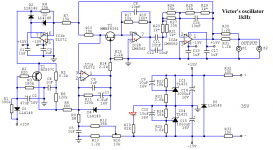
Here is the old 1kHz schematic.
If you wish to connect the external +/-15V supply, then you need to short resistors R23 and R25, otherwise the TL431 can be damaged.
If you wish to connect the external +/-15V supply, then you need to short resistors R23 and R25, otherwise the TL431 can be damaged.
Victor, can I just connect the new +/-15 to appropriate points for the opamps, and leave the TL431 stuff as it is, or will that cause problems?
Have you published a schematic and board layout, I can't find it online.
Jan
Attachments
If you have better regulators anyhow, why not just remove the 2x TL431's.
Afterall, they are not the lowest noise regulators you can have.
Patrick
Afterall, they are not the lowest noise regulators you can have.
Patrick
- Home
- Design & Build
- Equipment & Tools
- Low-distortion Audio-range Oscillator