I did not know of problems with COG caps. Probably manufacturing issues, just like everything else. Polystyrene would be the best choice for distortion and mica for stability but the sources for good cap film have all dried up and mica gets large and very expensive so they are not a practical option.
Jan just reduce the voltage across the resistor(s). Use series resistors rather than one and 1/2 watt if you have the space.
Yes. Look for the voltage coefficient of the R. That is the issue in that location ( Rf).
Dale are excellent, low cost and readily available.
THx-RNMarsh
Does anyone here have experience with distortion caused by (feedback) resistors? I am slowly finding out that at -120dB, EVERYTHING matters ...😱
Jan
Hi Jan,
Yes, in my book I show a curve of resistor distortion vs frequency that I measured. The idea was to measure resistor distortion that results from signal-induced temperature changes in the resistance element. The distortion increases as the frequency decreases, as expected.
This means that the feedback resistor in a power amplifier would like to be something like a 2 W metal film resistor. Note that when a resistor is operating at its rated power dissipation it is quite hot.
I have not been able to measure resistor distortion that appears to result from non-signal-induced temperature phenomena, but that does not mean it does not exist.
Cheers,
Bob
I have not been able to measure resistor distortion that appears to result from non-signal-induced temperature phenomena, but that does not mean it does not exist.
Cheers,
Bob
There are other distortion issues that show up in low cost types. The level in better resistors is measured as even order distortion products almost always a lot lower than the thermally induced distortion.
In a feedback application using say ten identical resistors in series feeding one to form a voltage divider I always thought was obvious to significantly teducevthrrmal tracking issues. It is important to use a zig zag for the chain of ten to reduce inductance.
Hi Jan
We have many very bright accomplished engineers here (including you) and reading most post it very obvious. We all learn from others.
When distortion components are to be very low close to the NOISE FLOOR every tiny thing matters.
I posted this: The Current 2 Voltage converter on the ATS2 DAC output was a big problem. The 0805 feedback was about 50mw and @ 10Hz the thermal time constant was a real distortion generator even though the resistor was 25ppm.
In POWER AMPLIFIERS the feedback resistor causes distortion. The higher the gain the worse it is. Voltage & Thermal coefficients make the resistor a SLINKY or BUNGY CORD even with the lowest ppm types, so use many smaller values to make the divider.
When @ Mackie the production engineering changed my 100 ohm ½ W through hole resistor to a 100 ohm 0805. It worked one time, as it was the RC filter for the 48v phantom power before opening.
I have worked to help all of my young engineers to read and understand the specification and limitations of each and every part used.
Duke
There are other distortion issues that show up in low cost types. The level in better resistors is measured as even order distortion products almost always a lot lower than the thermally induced distortion.
In a feedback application using say ten identical resistors in series feeding one to form a voltage divider I always thought was obvious to significantly teducevthrrmal tracking issues. It is important to use a zig zag for the chain of ten to reduce inductance.
I can only tell you that in Figure 13.2 of my book, a 1/4 W metal film 1k resistor subjected to 1/4 W dissipation had distortion down by 126 dB at 500 Hz, and the distortion was rising as frequency decreased, as expected for thermally induced distortion.
Now, in fairness, a resistor subjected to its rated dissipation will have relatively high thermally-induced distortion as compared to applications where is is subjected to, say 1/10 its rated power dissipation. So, for example, if my measurement floor at the time could have gone down to, say, -140 dB, and I tested a resistor at 1/10 its rated power, some other distortion effects not related to signal-dependent thermal variations might have showed up.
So my question is, are you referring to measurements you have made on resistor nonlinearity where the resistors were operated well below their rated power dissipation and the resulting distortions were below, say, -130 dB?
Cheers,
Bob
re: resistor distortion... I have not read this whole thread but just saw data from 1945 showing change of resistance with "impulse voltage" (apparently from spark-ignition studies).
Note that the resistance drops very steeply as you come zero to 200V, and curved.
Yes, these are "composition" resistors, today regarded as crap. Film resistors are significantly better; but a hundred dB better? Gotta check.
And yes the steady-state rating of the resistors is being grossly violated. (Practical ignition suppressing wires are glass fiber dragged in soot, spreading the stress over the full length of the wire.)
They say this of wire-wound:
"The fixed arms of the bridge may be composed of inductive wire-wound resistors. The inductance so introduced has only a negligible effect on the accuracy of measurement at the frequency of the pulse wave. A 10,000 ohm wirewound resistor, with zero-voltage coefficient when measured at 10,000 volts, reads within 0.5 percent of its resistance at 6 volts d-c."
Attachments

@Duke
you mentioned "In POWER AMPLIFIERS the feedback resistor causes distortion. The higher the gain the worse it is.". Is this because the Rf is loaded more at higher gain or the gain multiplying the distortion of Rf or both?
you mentioned "In POWER AMPLIFIERS the feedback resistor causes distortion. The higher the gain the worse it is.". Is this because the Rf is loaded more at higher gain or the gain multiplying the distortion of Rf or both?
Does anyone here have experience with distortion caused by (feedback) resistors? I am slowly finding out that at -120dB, EVERYTHING matters ...😱
Jan
I've been using Susumu 2012 RG series and they work just fine. I'm measuring distortion from my test amplifier circuits only a few dB different than the APx-555 residual, which is around -150 to -155dBc for 2nd harmonic and about -155 to -160dBc for 3rd harmonic. Given that everything seems to be muddled around the APx residual, and my circuits have more noise than the APx, I suspect that the real DUT performance is much better, but simply obscured by the analyzer residual and my extra DUT noise. Snaky things happen when the DUT is within the same basic region of performance of the analyzer, as you probably already know.
So, IMHO you have a long way to go before resistors are going to ruin your day - I can assure you that the Susumu RG series can do -120dBc easily, and certainly exceed -145dBc as well. Below that, my residual isn't really low enough to be fully authoritative. Or, my circuits exploit some special symmetry or magic juju that cancels all of the ills that they cause. 😀
For most gain resistors, I'm using the 10 ppm/ºC versions of the 2012 RG series, which are a little pricier than the standard 25 ppm/ºC versions, but I'm doing that primarily for CMRR and balance reasons, and not to mitigate thermal / signal effects. Still, they're pretty inexpensive, and for a small SMD chip, they perform extremely well.
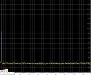
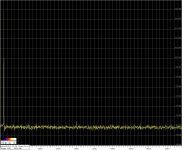
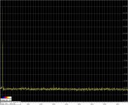
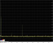
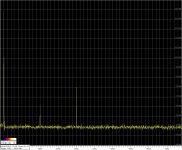
The question about resistors distortions is interesting, and I made some fresh measurements. Spectrum was measured via twin T notch. Scale adjusted at 3kHz, but 2kHz needs to add +4dB. The measurement schematic include 1kHz reference oscillator, LM4562 opamp in the inverted mode and transfer ratio near to -1 with the high grade thru hole metal film feedback resistor. The resistors under test was connected as input resistor. Voltage across the input resistor around 2,5V RMS. Value 6,8 khom.
1) reference measurement was done two times with two different case style high grade thru hole metal film resistors - no distortions visible.
2) Multicomp metal film MELF 0204
3) Susumu metal film 0805
4) 5) 6) probably Yageo thick film RC1206 - three examples from the same cutted tape
1) reference measurement was done two times with two different case style high grade thru hole metal film resistors - no distortions visible.
2) Multicomp metal film MELF 0204
3) Susumu metal film 0805
4) 5) 6) probably Yageo thick film RC1206 - three examples from the same cutted tape
Attachments

Does anyone here have experience with distortion caused by (feedback) resistors? I am slowly finding out that at -120dB, EVERYTHING matters ...😱
Jan
Never mind -120dB. I found bad choice of feedback resistor (thick film surface mount) had -100dB effects or worse.
Suzy's Blog: Measuring a MOSFET Power Amplifier.
Bob,
Using my bridge technique I can look well below -180 dB from the excitation level. I am away from where my test results are stored so it will be a bit before I can post images. I recall using resistors well below power ratings.
The bottom line is no component is perfect but with good component choices and attention to design one may be able to approach errors below -160 dB of the signal level. At those levels noise is the issue.
It looks like large through hole resistors are preferred as an easy solution.
At low frequencies any thermal coefficients will show up as the thermal time constant is short enough to allow modulation of the resistance. In this case (below 120 dB) it is part per billion changes that show up. On the foil resistors its sort of worst case since the foil's native thermal is "counteracted" by the substrate's thermals. You can dive into the world of ultraprecision wirewounds to see solutions. Resistors - Oil Filled - Epoxy Encapsulated | Ohm-Labs, Inc. However I was told the recipe for Evenohm has been lost so the worlds supply is finite.
FWIW the amplifier sections of my Optimation calibrator use Vishay S106 2W resistors for the feedback to get stability. It also has something like 60 S102's in the divider. The Vishay salesman covered his nut with that sale.
Last edited:
The Vishay Beyschlag MELF is one of few SMD resistor types that is thin film, apart from Susumu.
Patrick
Patrick
There are a lot of thin film SMD resistors out there. Lots. Pretty sure every major brand makes at least one line.
Digikey has ~41k different parts from 14 manufacturers in thin film SMD.
Digikey has ~41k different parts from 14 manufacturers in thin film SMD.
Last edited:
It looks like large through hole resistors are preferred as an easy solution.
At low frequencies any thermal coefficients will show up as the thermal time constant is short enough to allow modulation of the resistance. In this case (below 120 dB) it is part per billion changes that show up. On the foil resistors its sort of worst case since the foil's native thermal is "counteracted" by the substrate's thermals. You can dive into the world of ultraprecision wirewounds to see solutions. Resistors - Oil Filled - Epoxy Encapsulated | Ohm-Labs, Inc. However I was told the recipe for Evenohm has been lost so the worlds supply is finite.
FWIW the amplifier sections of my Optimation calibrator use Vishay S106 2W resistors for the feedback to get stability. It also has something like 60 S102's in the divider. The Vishay salesman covered his nut with that sale.
Yeah, as you mentioned, according to Bruce Hofer the "trick" the foil resistors use makes them a little worse than a standard thin film at low frequencies. There are a few good options for thin film with very low tempco, including the Susumu, a few Vishays, and Stackpole.
I don't like through-hole for layout so I'd probably use series / parallel combinations where the voltage and power becomes an issue.
Guys, thanks for all the good tips. Seems like the collective intelligence here has it pretty well covered. I should get my act together with this.
Re: the 'Bruce Hofer' trick on using series Rs in a feedback leg: the idea is to use specifically the same R types and value in the feedback leg as the ground leg. Example: a gain of 22 with a 1k to ground would required a series R string of 21 times the exact same 1k as the ground leg.
That way, the tempco and voltco effects fully cancel to a first order.
Jan
> There are a lot of thin film SMD resistors out there. Lots.
I was referring to MELF resistors.
Not all are thin film. Only a few types are.
Cheers,
Patrick
I was referring to MELF resistors.
Not all are thin film. Only a few types are.
Cheers,
Patrick
> There are a lot of thin film SMD resistors out there. Lots.
I was referring to MELF resistors.
Not all are thin film. Only a few types are.
Cheers,
Patrick
I see, the wording in your original post had me confused.
I don't see a lot of reason to use MELF, personally. There are enough good thin-film resistors in the standard SMD form factor.
- Home
- Design & Build
- Equipment & Tools
- Low-distortion Audio-range Oscillator