Jan one more thing, if you can afford the parasitic place a copper pour on the surface below the resistors to spread the heat. Mount the resistor tightly against it. It doesn't have to be grounded.
Last edited:
It has not been a big issue but it is an issue for large FFT's since the harmonics change during the measurements and sometimes just go away as it drifts from bin to bin.
There is an article on flattop windows with extremely low skirts developed for testing modern A/D's and DAC's. The flat top spans several bins.
Jan one more thing, if you can afford the parasitic place a copper pour on the surface below the resistors to spread the heat. Mount the resistor tightly against it. It doesn't have to be grounded.
Good tip. I can use oversize pads, both sides, and stitch together. Largely automated in my Proteus.
Jan
Good tip. I can use oversize pads, both sides, and stitch together. Largely automated in my Proteus.
Jan
Yes
Hi David
Your answer was posted by Jan #7257
The big problem is with hi gain Power Amplifier (lots of heat) and 22 resistors or more the spacing needed could get you into different thermal path's. What amount of non linearity do you need or want?
Duke
@Duke
you mentioned "In POWER AMPLIFIERS the feedback resistor causes distortion. The higher the gain the worse it is.". Is this because the Rf is loaded more at higher gain or the gain multiplying the distortion of Rf or both?
Your answer was posted by Jan #7257
The big problem is with hi gain Power Amplifier (lots of heat) and 22 resistors or more the spacing needed could get you into different thermal path's. What amount of non linearity do you need or want?
Duke
Hi David
Your answer was posted by Jan #7257
The big problem is with hi gain Power Amplifier (lots of heat) and 22 resistors or more the spacing needed could get you into different thermal path's. What amount of non linearity do you need or want?
Duke
No need. Just a general question.
Hi David
Your answer was posted by Jan #7257
The big problem is with hi gain Power Amplifier (lots of heat) and 22 resistors or more the spacing needed could get you into different thermal path's. What amount of non linearity do you need or want?
Duke
The idea would be not to make one long string. Making resistor networks out of unit values is pretty old, the problem is the gain goes as the ratio but power as the ratio squared making things clumsy for large gains.
Have been playing with my new old AP SYS2722. Attached THD residual of the 2722 analog generator, as well as Viktors 1kHz oscillator, both at 1kHz, 2VRMS out.
Interestingly, the Viktor shows lower residual for 2nd and 5th, better than the AP. It also shows that going to balanced probably is not worth it.
Viktor, if you read this, is this typical for your unit? If you only could get rid of that 3rd .. ;-)
The specs for the 2722 are about 4dB better than shown here, but I am still waiting for the calibration kit from Mr. AP to arrive.
Comments invited.
Jan
Attachments
Last edited:
No not yet, only 1V and 2V, similar. At 0.5V, similar; my lowest setting on the Viktor is 300mV but that pot position is not stable.
I wanted to establish a baseline for the tracking notch prototype.
Edit: Viktor 0.5V attached
Jan
I wanted to establish a baseline for the tracking notch prototype.
Edit: Viktor 0.5V attached
Jan
Attachments
Last edited:
Hi Jan
I assume that you were usng a notch fiter to knock out the fundamental. What filter was that? I would be very interested in seeing the schematic if you don't mind sharing it.
Just had a thought - was that the AP in action and not a descrete notch filter?
Kind regards from a cold UK
Mike
I assume that you were usng a notch fiter to knock out the fundamental. What filter was that? I would be very interested in seeing the schematic if you don't mind sharing it.
Just had a thought - was that the AP in action and not a descrete notch filter?
Kind regards from a cold UK
Mike
Hah! It is the build-in notch in the AP. No schematic available....
Edit: this is the System One notch in concept. 2-stage 4-pole.
A86, A87, A88 and A89 are MDACs.
Jan
Edit: this is the System One notch in concept. 2-stage 4-pole.
A86, A87, A88 and A89 are MDACs.
Jan
Attachments
Last edited:
Jan. I did basically the same as you with my Victor oscillator but with a passive notch. My result are much better and I suspect that your distortion origins from the AP's notch.
I had the same problem with my notch before changing the notch caps to a massive parallelled C0G type.
Ser the result here. Low-distortion Audio-range Oscillator
I had the same problem with my notch before changing the notch caps to a massive parallelled C0G type.
Ser the result here. Low-distortion Audio-range Oscillator
Jan Victor's oscillator has no third. At lease not above the noise floor.
I think this is the AP.
I think this is the AP.
Jan. I did basically the same as you with my Victor oscillator but with a passive notch. My result are much better and I suspect that your distortion origins from the AP's notch.
I had the same problem with my notch before changing the notch caps to a massive parallelled C0G type.
Ser the result here. Low-distortion Audio-range Oscillator
There is one active circuit in the AP before the notch, which is the balanced to single-ended converter. Even when you use the se BNC input, it is still treated as bal by the ranging circuits until it goes into the notch and further processing/measuring. The ranging is passive for these levels.
@Davada yes this might be the AP.
Your results are indeed extremely low. How much is the fundamental suppression by the notch, I can't see it in your graph.
Edit yes calc from numbers, about -80dB.
Jan
Last edited:
Please can you show the bottom side of your 1kHz board for to identify the oscillator version?Viktor, if you read this, is this typical for your unit? If you only could get rid of that 3rd .. ;-)
Jan
P.S. Probably Armand has last oscillator version.
Vic.
Last edited:
As a comparison, here is a loopback from my APx-555, which is a heck of a lot cleaner, possibly implying that you could squeeze a lot more out of your 2722.
I'm using the advanced analog generator and analyzer, with a test frequency of 0.99609kHz, since the fundamental and harmonics line up with a 192kHz FFT better than 1kHz. The residual at ~2kHz is a tiny bit lower than 1kHz, but the differences are not huge, so I included the 1kHz FFT here. The oscillator level is +6dBV and I'm using a balanced connection with a 2' Mogami 2534 XLR cable from the output XLR to the input XLR. +6dBV is a good choice, since the generator can drive the 200kΩ analyzer load easily at this level, and the noise floor will be lower than using lower drive levels. This particular graph was made with an additional 4kΩ load in parallel with the analyzer input, in order to make a loopback comparable to the circuit I was testing at the time, but the results here are not significantly different than with the stock 200kΩ balanced input load.
The analyzer is set to a 192kHz sample rate with a 256K point FFT. I'm using 128 synchronous averages to grind the noise floor down, with the Dolph Chebyshev 250dB window function. I set the X axis to linear frequency, because I feel that it makes more sense with an FFT, due to the linear bin widths vs. frequency - sorry if it looks odd.
With this setup, the analog generator will drift slightly during the FFT averaging time, but the 256K FFT and 192kHz sample rate make the FFT bins wide enough so that energy does not spill much into adjacent bands, making the spur levels reasonably accurate. Sufficient warmup time (an hour or so) assures that the frequency drift is minimal.
Using power averages, and not synchronous averages, you can get essentially the same results, but with an obviously higher noise floor, which obscures all but the 2nd and 3rd harmonics. So, I'm using synchronous averaging, which seems to be more reliable overall.
The FFT graph from the 555 seems to splice in the original waveform near the fundamental, making the FFT look like the actual signal presented to the input, and not just the output of the notch filter, which is what you see from the older analyzers. So, the fundamental peak is in the graph, but I clipped the fundamental peak away since I don't care about it.
An important issue is that the levels in my graph are dBV, and not dBr, so subtract the 6dBV drive level from the spur levels in my graph to get the dBr values to make a valid comparison to your graph.
These 555 values are about 20dB better than the 2722 graph you posted, and while the 555 should be better than the 2722, some people claim that it isn't, and I doubt that it's 20dB better. Still, something needs to be harmonized here - either I'm living in a fantasy land, the 555 is drastically better than the 2722, or you're throwing away 20dB+ of residual somehow.
Attachments
There is one active circuit in the AP before the notch, which is the balanced to single-ended converter. Even when you use the se BNC input, it is still treated as bal by the ranging circuits until it goes into the notch and further processing/measuring. The ranging is passive for these levels.
@Davada yes this might be the AP.
Your results are indeed extremely low. How much is the fundamental suppression by the notch, I can't see it in your graph.
Edit yes calc from numbers, about -80dB.
Jan
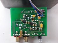
Spot on. (Pic 1) It's a twin-T notch with Susumu metal film 0805 resistors (1,5k and 3,1k) with three 100 ohm multiturn potmeters in series with all at enables fineadjustment of the notch down to about -80dB.
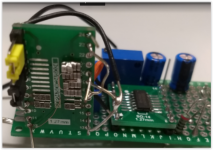
First I used PET capacitors in the notch filter, but that gave me much worse results. I then modded the circuit to this ugly creature with about 20-25 0805 C0G capacitors in series paralell to match the doube value required in twin-T design. (pic2)
That did the trick and I am very pleased with the result.
In the process Victor adviced me to also test the Wima FKP2 or polystyrenes from LCR. I have not come around to that yet since the performance is more that good enough for my purposes now.
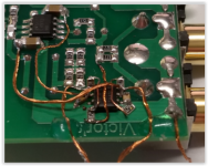
I have also added a OPA1632 on the output to give me balanced singnal to my amplifier testing (pic3).
With this in place I get around -140dB second and third order distortion. If this is from poorly matched resistors, the OPA1632 itself or from the analyser (with its built in notch) is unknown. Anyway it is much lower than the amp I am working on.
Attachments

Hi Monte, that's quite useful!
Yes as far as I know, they do splice in the fundamental.
In my graphs, I've used power averaging; sync averaging probably would give a lower floor but as it is the 2nd and 3rd harmonics already stick out. I'll try some of the other settings.
In Samuel Groner's analyzer comparison linked to somewhere above, the 555 comes out better especially above a few kHz but not so much.
OTOH, my results match the 'typical' curves in the 2722 spec sheet.
More testing to be done...
Edit I have used the internal loopback, reading from AGen.
Jan
Last edited:
- Home
- Design & Build
- Equipment & Tools
- Low-distortion Audio-range Oscillator