If Vicktors' was still selling his on eBay I probably would not have gone off on this tangent.
I get the tangent thing, but FYI just PM Victor and he'll provide any frequency you may need.
BK
If you really want to go crazy, you can do an 8-phase rectifier by combining the in-phase and quadrature signals available in a SVO to create signals at 45-degree intervals.
Cheers,
Bob
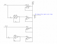
I'm not sure how to get a 45 degree phase from an SVO or maybe I'm overlooking something. Here is the low parts count 4 phase solution I used. It takes advantage of the open collector LM339 which will behave as an amplifier with pull down but no pull up. No diodes or diode drops to deal with. Trimming to get 4 peaks at exactly the same level would be an issue. Speed up tricks etc. to be added. Still not as good as a sample and hold-track and hold but fewer parts and no fast edges.
Attachments
What I meant was...
Ok, now we are in sync.
Realistically I don't think there's an issue...in a fixed-frequency circuit...
Yes, probably fine for a fixed frequency circuit, your implementation looks nice and tidy, and I believe your claim that it locks without problems.
You have a lot of control authority because the VCA isn't actually decoupled with a current divider.
I expect there would be a minor trade-off with noise, as you turn the VCA gain down the noise does not drop proportionally, as it would with a current divider.
But the THAT2180 is fairly quiet so presumably it's not a problem.
I still think there are benefits of a solution where the gain control side chain is bipolar and can be trimmed to a null.
One is an issue touched upon by Bob Cordell.
Ideally it is possible to switch frequency band without any disturbance, if the control loop nominal contribution is zero there is no need to pre-condition capacitors.
Best wishes
David
...Here is the low parts count 4 phase solution I used.
That seems a clever solution, do you have one for the "sum of two squares"? 😉
Best wishes
David
I don't have one but I found this which is similar: A Circuit for the Square Root of the Sum of Two Squared Voltages using an IC LM311 Open Collector Comparator | Selvam | Engineering, Technology & Applied Science Research I would not use it since it will generate a lot of HF junk. Normally you would use an analog multiplier or one of the dedicated chips for that.
...Normally you would use...
Decent multipliers aren't that cheap. Not a major expense but a clever, cheap solution would be nice.
What "dedicated chips" did you have in mind?
Thanks for the reference, maybe more comment after I read it.
Best wishes
David
This is what I was thinking: RMS to DC Converters | Analog Devices or http://cds.linear.com/docs/en/datasheet/1966fb.pdf One of the ADI parts is less than $3. I'm not sure why those and VCA's aren't used more in these oscillators. I'm sure something obvious will make it all clear if I actually try to use them. Maybe its that all the designs we look at originated 30 years ago when these were not cheap.
I don't think an RMS converter does what we want.
We want to square two separate inputs and add them essentially instantly, not square an input, take a mean value with a capacitor, over many periods and then take the root.
The AD unit could omit the capacitor and be used just as a squarer but then we would need two.
Best wishes
David
I'm not sure how to get a 45 degree phase from an SVO or maybe I'm overlooking something. Here is the low parts count 4 phase solution I used. It takes advantage of the open collector LM339 which will behave as an amplifier with pull down but no pull up. No diodes or diode drops to deal with. Trimming to get 4 peaks at exactly the same level would be an issue. Speed up tricks etc. to be added. Still not as good as a sample and hold-track and hold but fewer parts and no fast edges.
I haven't seen the LM339 used as a rectifier element before. Did you see this in an app note somewhere. It is a clever, low-parts-count idea.
What about the speed/delay of the LM339? For each one, when the signal at its input goes below the stored output level, the comparator turns on and drags the output level down until the output level is as low as the negative peak of the input signal. However, in a quiescent state, when the oscillator has stabilized and needed corrections are very small, the amount of charge that needs to be removed from the storage capacitor is very small - simply the amount of charge that the pull-up resistor put into the capacitor since the last correction (in the case here, 1/4 cycle). Moreover, the 339 open-collector output turns on hard, so a lot of current can flow over this very short turn-on interval.
This leads me to wonder how small a very narrow pulse can be made by the LM339 at its output so as not to cause, at minimum, errors in the rectified value. This would also seem to be more of an issue at higher frequencies, like 20kHz or even 200kHz.
Any thoughts?
Cheers,
Bob
I haven't seen the LM339 used as a rectifier element before. Did you see this in an app note somewhere. It is a clever, low-parts-count idea.
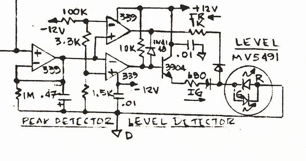
Here are some LM339-base comparator peak detectors I've used dating back to the 1970s at Micmix. They make very good peak detectors but not so good absolute value circuits. I would not want the high-speed edges in an ultra pure oscillator.
This one is a half-wave comparator-based detector which produces a negative output.
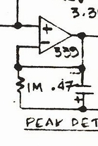
A comparator-based peak detector using an LM339 open collector output.
This one, when fed with anti-polarity inputs is full-wave. It uses boost transistors. Unless diodes are in series with the bases the output is limited to the Rev Vbe voltage of the transistors. The feedback to the LM339s from the emitters has been cropped so you'll need to use your imagination.
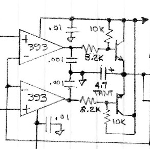
A comparator-based peak detector with NPN Boost transistors.
A two-color overload indicator using a comparator-based peak detector.
I think there is also a reference to comparator-based peak detector circuits in Horwitz and Hill First Edition.
I collect level detection circuits: Level Detectors, Absolute Value, Peak and RMS
Testing the Cordell Rectifier
I had a chance to try Bob's rectifier and it is ultra clean. I'll post oscillograms.
The only issue I found with it, which is easily-correctable, is that the maximum output level is limited by the reverse breakdown of the transistor's B-E junction. The detector starts to clip around 4V peak. The clipping causes start-up issues since the detector cannot sense on power-up that the oscillator is running at the rails.
Once start-up occurs the Cordell rectifier works very,very well. I saw 1 ppm out of the PCM4222 for the first time. The absolute value waveform has no hard corners.
Detector clipping is easily solved by simply padding the rectifier input which is something I think I want to do anyway. If you're going for say 10V peak output from the oscillator you really don't want the detector broadcasting high-level harmonics. I found this to be the case with the Janasek rectifier.
The second out-of-polarity output available from the Wien bridge oscillator was used to rectify the negative waveform. No additional inverter is required and the symmetry is excellent without trim. Once a pad is added a trim will be required.
Last edited:
I haven't seen the LM339 used as a rectifier element before. Did you see this in an app note somewhere. It is a clever, low-parts-count idea.
Any thoughts?
Cheers,
Bob
Internally the LM339 is part of an opamp. You can actually trick it into working as a crude opamp with a pullup resistor. None of the internals are logic and they don't seem to saturate which is important for a comparator. Its quite similar to a rectifier with feedback. Since its running in the linear mode when charging the cap its plenty fast.
Here are the more conventional ways to get there: http://ww1.microchip.com/downloads/en/AppNotes/01353A.pdf
As you can see above its not a new idea. I don't think any of the genuinely fast comparators would work for this. They all have internal logic and no linear path from input to output unlike the LM339.
Internally the LM339 is part of an opamp. You can actually trick it into working as a crude opamp with a pullup resistor.
The system probably would be tended to oscillate because of the phase shift. The comparator has no internal phase correction for to work stable in the linear mode. I saw these problems in reality with the similar comparator LM393.
The LM339 also has an identical dual the LM393.
They make very fast peak detectors particularly when buffered by external transistors. You can make an OK absolute value out of them by using a small output C and/or current source. As detectors they have low offset and good low-level linearity.
I wanted to show a comparison of the "purity" of an active rectifier to a biased diode open loop rectifier.
For these photos I had replaced the biased transistor rectifier with diodes to allow the Cordell rectifier to exceed the rev-Vbe breakdown of the transistors. (To allow start-up.) The waveforms look almost identical to the transistor-based version.
This is a typical active rectifier taken from Janasek. It has a kink.

This is a biased diode rectifier based on the Cordell topology at 200 mV peak. No kink.

This is the biased diode rectifier at 2V peak. I overlaid the input.

As I mentioned earlier I didn't think hard corners/fast edges were good to have in the box. The biased diode absolute value doesn't have the waveform kink.
They make very fast peak detectors particularly when buffered by external transistors. You can make an OK absolute value out of them by using a small output C and/or current source. As detectors they have low offset and good low-level linearity.
I wanted to show a comparison of the "purity" of an active rectifier to a biased diode open loop rectifier.
For these photos I had replaced the biased transistor rectifier with diodes to allow the Cordell rectifier to exceed the rev-Vbe breakdown of the transistors. (To allow start-up.) The waveforms look almost identical to the transistor-based version.
This is a typical active rectifier taken from Janasek. It has a kink.
This is a biased diode rectifier based on the Cordell topology at 200 mV peak. No kink.
This is the biased diode rectifier at 2V peak. I overlaid the input.
As I mentioned earlier I didn't think hard corners/fast edges were good to have in the box. The biased diode absolute value doesn't have the waveform kink.
Thank you.
It's been bugging me too and I'm not sure ripple is the culprit.
The Janasek, or almost any "class-B" active rectifier have "hooks" and asymmetry in the waveform. The HF content may or may not pass through the control loop but it seems like it could radiate. You can see at zero crossing a discontinuity.
That may be why Cordell, Smith, Bateman et al didn't use conventional feedback-type absolute value circuits.
I'm curious about experimenting with their rectifiers and biased ones like here: THAT2252 RMS Detector Replacement Using A THAT300 Array (without the log stage) or one based on Graeme: Level Detectors, Absolute Value, Peak and RMS
The biased diode absolute value looks cleaner:

Biased Diode Absolute Value 1kHz 2V Peak
There may be some magic in Viktors' half-wave detector.
Large dynamic range isn't required of the detector by any means but it would seem that a clean waveform is.
something to take note of.
a full wave rectifier injects twice the frequency.
so if it is controlling the amplitude then you are injecting a second harmonic.
a very good reason for a half wave rectifier.
something to take note of.
a full wave rectifier injects twice the frequency.
so if it is controlling the amplitude then you are injecting a second harmonic.
a very good reason for a half wave rectifier.
I don't get this logic. While its true that a FWR injects second harmonic, it also injects much higher harmonics as well. A half-wave rectifier injects everything from fundamental on up. The higher harmonic frequencies injected by a given rectifier will receive more attenuation by the control loop filter than the lower harmonics, for a given amount of loop stability and settling quality.
A FWR has p-p ripple equal to the peak value of the signal. A 4-phase rectifier has p-p ripple only on the order of 30% of the peak value of the signal, and its lowest ripple frequency (in the ideal case) is 4X the fundamental, as compared to 2X the fundamental in a FWR. This means that in a first-order control loop filter, its harmonics will see 6dB more attenuation than those from a FWR.
Cheers,
Bob
All of the current AGC elements (FET or analog multiplier) have full bandwidth so any stuff on the control input comes through the system. In the jfet case I encountered the problem with the KH4400. I can null the 2nd from the jfet with the distortion trim. But the harmonic spectrum on the gate of the JFET is also on the main output (attenuated a lot but still there). The higher order harmonics are attenuated but not gone. I was speculating about taking an inversion of the signal going to the gate and adding it to cancel the harmonics. Not sure that would work however.
I'm not sure if the linearity of the AGC element is a problem until this issue can be resolved.
I'm not sure if the linearity of the AGC element is a problem until this issue can be resolved.
Am I the only one who uses a multi-pole low pass filter after the rectifier? More attenuation and faster settling...
Am I the only one who uses a multi-pole low pass filter after the rectifier? More attenuation and faster settling...
My design actually is multipole, but it also has some zeros. Going straight mutlipole for an oscillator that is tunable over a decade can be difficult to stabilize. As long as good agc loop stability can be maintained over the required operating range, multipole is a good thing.
BTW, absence of high-order harmonics in the oscillator output is important and very desirable, but often will have little influence on the THD we ultimately measure because they are usually fairly small compared to 2nd, 3rd, 4th. So it doesn't help the specsmanship very much 🙂.
Cheers,
Bob
Cheers,
Bob
And potential for instability. However I have seen designs with more than one integrator on the level detector.
Its important to have a full perspective on the requirements. For a single frequency oscillator that can have a longer startup time major filtering is not a big issue. Victor's oscillator takes 5-10 seconds to stabilize in output. For a tunable oscillator that needs to be part of a more complex system that may not be workable. I have some oscillators with really low distortion that have instant (by human standards) stability but pretty complex AGC's. If its part of an ATE system waiting 10 seconds between settings could be a non-starter.
Its important to have a full perspective on the requirements. For a single frequency oscillator that can have a longer startup time major filtering is not a big issue. Victor's oscillator takes 5-10 seconds to stabilize in output. For a tunable oscillator that needs to be part of a more complex system that may not be workable. I have some oscillators with really low distortion that have instant (by human standards) stability but pretty complex AGC's. If its part of an ATE system waiting 10 seconds between settings could be a non-starter.
- Home
- Design & Build
- Equipment & Tools
- Low-distortion Audio-range Oscillator