I wonder if anyone has actually tried simulating the Viktor oscillator in Spice ?
I tried today. The LM4562 model is faulty, so needs fixing later on.
For a quick check I tried using LT1115 instead, but could not get it to oscillate.
Anyone has more success ? Would be grateful for any pointers.
(And hope Viktor wouldn't mind, since schematics is already in public domain.)
Many thanks,
Patrick
.
I added a sinus current source with 1k, 100uA and 10 cycles to the neg.
input of U2b to help startup.
As soon as the current source switches off, the oscillation decays rapidly.
Maybe there is something wrong with your model?
Patrick,
Your Victor oscillator schematic is different from the one I used, especially around the FET. I used the one Victor first posted in 2012 here http://www.diyaudio.com/forums/equipment-tools/205304-low-distortion-audio-range-oscillator-21.html#post3116055
Your Victor oscillator schematic is different from the one I used, especially around the FET. I used the one Victor first posted in 2012 here http://www.diyaudio.com/forums/equipment-tools/205304-low-distortion-audio-range-oscillator-21.html#post3116055
Here is the last actual schematic:
http://content32-foto.inbox.lv/albums/e/elterra/SchematicN5/1kHzN5.jpg
Victor.
http://content32-foto.inbox.lv/albums/e/elterra/SchematicN5/1kHzN5.jpg
Victor.
I plead guilty of not reading all 661 pages in this thread.
I wanted to share with the readers of this forum my recent experiments with Viktors' and Janasek's designs modified to use a THAT2180 VCA in a subtractive gain control mode. This keeps the VCA in deep attenuation approximately -45 dB.
The tests have been made on a Protoboard and I have not yet constructed a notch filter. It is believed that the 2 ppm distortion that I'm reading is dominated by the PCM4222 converter.
This is the schematic without the control loop:
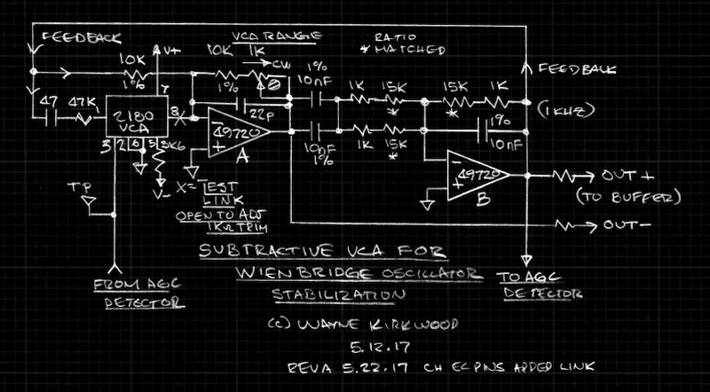
Subtractive VCA Stabilizes Ultra Pure Low Distortion Wien Bridge Oscillator
You will find examples of the Hood, Cordell, Smith, Bateman, Williams, Mickevics and Janasek ultra pure sub-ppm oscillators along with preliminary measurements of the THAT2180 VCA-based design here:
Super Low Distortion Ultra Pure Audio Oscillators Revisted
I wanted to share with the readers of this forum my recent experiments with Viktors' and Janasek's designs modified to use a THAT2180 VCA in a subtractive gain control mode. This keeps the VCA in deep attenuation approximately -45 dB.
The tests have been made on a Protoboard and I have not yet constructed a notch filter. It is believed that the 2 ppm distortion that I'm reading is dominated by the PCM4222 converter.
This is the schematic without the control loop:
Subtractive VCA Stabilizes Ultra Pure Low Distortion Wien Bridge Oscillator
You will find examples of the Hood, Cordell, Smith, Bateman, Williams, Mickevics and Janasek ultra pure sub-ppm oscillators along with preliminary measurements of the THAT2180 VCA-based design here:
Super Low Distortion Ultra Pure Audio Oscillators Revisted
Last edited:
Great work. The overview on the other forum is a nice summation of some of the current solutions.
The TI PCM4222 is good and i used it until I got the demo board for the AK5394A, which was 10 dB or more better.
Based on what i have done recently with the KH4400 http://www.diyaudio.com/forums/equipment-tools/306186-kh4400a-upgrades.html#post5041390 I'm beginning to think the level detector etc. is a significant limitation. The KH4400 harmonic residue pretty much matches the harmonics in the AGC detector's output. Its either the detector or the AGC element with current good opamps. Victor's oscillator is the best I have with harmonics in the -140 dB or lower range. However the settling time is slow, about 5 seconds for 1 KHz on my sample. Even the KH4400 is not quick to settle.
Great work. The overview on the other forum is a nice summation of some of the current solutions.
Thank you.
I'm beginning to think the level detector etc. is a significant limitation.
It's been bugging me too and I'm not sure ripple is the culprit.
The Janasek, or almost any "class-B" active rectifier have "hooks" and asymmetry in the waveform. The HF content may or may not pass through the control loop but it seems like it could radiate. You can see at zero crossing a discontinuity.

That may be why Cordell, Smith, Bateman et al didn't use conventional feedback-type absolute value circuits.
I'm curious about experimenting with their rectifiers and biased ones like here: THAT2252 RMS Detector Replacement Using A THAT300 Array (without the log stage) or one based on Graeme: Level Detectors, Absolute Value, Peak and RMS
The biased diode absolute value looks cleaner:

Biased Diode Absolute Value 1kHz 2V Peak
There may be some magic in Viktors' half-wave detector.
Large dynamic range isn't required of the detector by any means but it would seem that a clean waveform is.
Great work. The overview on the other forum is a nice summation of some of the current solutions.
The TI PCM4222 is good and i used it until I got the demo board for the AK5394A, which was 10 dB or more better.
Based on what i have done recently with the KH4400 http://www.diyaudio.com/forums/equipment-tools/306186-kh4400a-upgrades.html#post5041390 I'm beginning to think the level detector etc. is a significant limitation. The KH4400 harmonic residue pretty much matches the harmonics in the AGC detector's output. Its either the detector or the AGC element with current good opamps. Victor's oscillator is the best I have with harmonics in the -140 dB or lower range. However the settling time is slow, about 5 seconds for 1 KHz on my sample. Even the KH4400 is not quick to settle.
Two quick experiments will usually tell you whether the dominant source of distortion is the agc control loop (e.g. level detector) or the agc element.
1. cut in half the control loop integrator gain. If this reduces the distortion, it tends to point to the control loop as the major contributor. This step will often slow settling time, and in some cases may even cause the loop to become unstable, so there is no free lunch in cutting distortion.
2. Cut the signal operating level of the agc control element (e.g., the JFET) in half. If the distortion goes down significantly, this points to the agc element as the dominant source of distortion. Once again, there is no free lunch. Doing this will cut in half the agc control range (authority). Alternatively, cut in half the operating level of the agc element and double the gain of its signal injection into the oscillator loop after the agc element. This keeps the agc authority the same, but increases the oscillator noise that may be injected by the circuitry related to the agc element.
Note that these two experiments are described largely in terms of the JFET-controlled state variable oscillator i use, but the same experimental concepts can usually be applied to other oscillator topologies and control schemes.
The above also assumes that the dominant source of distortion is not the operational amplifiers. However, the results of these two experiments can give some insight as to whether the op amps are causing significant distortion. For example, if neither experiment leads to a reduction in distortion, the op amps can be suspected. Note also that in a SVO, measuring distortion at the outputs of the 2 integrators and comparing results can provide insight as to op amp distortion contributions. Distortion injected by the agc control circuit or the agc element should be smaller at the output of the second integrator if the op amps are not contributing distortion.
Finally, be sure that the agc level detector (e.g., full-wave rectifier in a simple design) does not have an opportunity to back-inject distortion into its signal pick-off point. A simple buffer helps in this regard.
Two full-wave detectors working in parallel, fed from the in-phase and quadrature outputs available in a SVO, can significantly reduce distortion from the level detector.
Cheers,
Bob
Finally, be sure that the agc level detector (e.g., full-wave rectifier in a simple design) does not have an opportunity to back-inject distortion into its signal pick-off point. A simple buffer helps in this regard.
I agree. I found I could make it cleaner at higher output levels simply by attenuating the input to the absolute value circuit. Bateman did that as well. The added source impedance seen by the rectifer's input isolated it from the source pick-off point and the rectifier signal swing and currents are smaller. The impedance in Smith is pretty high too - there are 100KΩ resistors in series with the unbuffered rectifier diodes.
I ran experiments similar to (1) and (2) and it made me conclude that the 2 ppm I was seeing (or the majority of it) was related directly to the level seen by the A/D. I had to seriously break the oscillator control loop before it appeared to contribute THD. You may not have seen my post at the Pro Audio Design Forum but the -25 dBFS knee in the distortion is consistent with the converter specification.
BTW Bob I particularly like the rectifier you used in your THD analyzer. It's buffered, has a symmetry trim and none of the op amps run open loop at zero cross.
Last edited:
The traditional best practice is a sample and hold + track and hold. You should get very little ripple. But those chips are not popular, expensive and in some cases obsolete.
A 4 phase rectifier is a good solution and can be done with a single LM339 + 2 opamps.
DavidA has a really trick scheme using an ADC as a sampler and a multiplying DAC for an AGC element. You can see how with the addition of a micro this could do a lot.
A 4 phase rectifier is a good solution and can be done with a single LM339 + 2 opamps.
DavidA has a really trick scheme using an ADC as a sampler and a multiplying DAC for an AGC element. You can see how with the addition of a micro this could do a lot.
Helper circuits can be used to keep the oscillator under control during large excursion from
mode changes.
The schematic below illustrates a simple circuit the adds damping to the oscillator on negative signal swing. The pot R10 at Q5 adjusts the threshold at which the Jfet begins to turn on.
This allowed the multiplier authority to be greatly reduced by increasing the amount of decoupling between the multiplier and oscillator. The decoupling was increase by 20dB for a total of -30dB decoupling. This lowered the noise and distortion contribution of the multiplier significantly.
This is one example of secondary control.
Attachments
Last edited:
...modified to use a THAT2180 VCA in a subtractive gain control mode. This keeps the VCA in deep attenuation approximately -45 dB.
Is there any benefit to make it subtractive?
My first impression is that it's essentially equivalent to have the main loop trimmed to within a fraction of a dB of oscillation and have the gain control element decoupled by a certain number of dB, whether the gain control is added or subtracted.
The ability to eliminate an I to V step is nice in your specific implementation, of course, but I mean more broadly.
The Janasek, or almost any "class-B" active rectifier have "hooks" and asymmetry in the waveform...
I am interested in a tuneable oscillator and the "Sin^2 + Cos^2" amplitude calculation looks theoretically nice to keep the amp stable as the frequency potentiometer is swept.
I had not considered the potential extra benefits of the lack of "hooks"
Have you considered the sum of squares approach?
Best wishes
David
Last edited:
Note in my oscillator two things help in the tradeoff between settling time and distortion injected by the control loop. First, when the amplitude error is large, as after a range switch. diodes D2 and D3 increase the gain of the integrator by a factor of 100 for fast settling.
Secondly, each frequency range of the oscillator has its own control loop filter that is optimized for that range. At low frequencies, a large time constant is needed to filter the ripple from the rectifier, but at higher frequencies, a much smaller time constant will do. Note also that the capacitors in these range-selected filters are pre-charged to the operative voltage of the previously-operating range.
Cheers,
Bob
The traditional best practice is a sample and hold + track and hold. You should get very little ripple. But those chips are not popular, expensive and in some cases obsolete.
A 4 phase rectifier is a good solution and can be done with a single LM339 + 2 opamps.
DavidA has a really trick scheme using an ADC as a sampler and a multiplying DAC for an AGC element. You can see how with the addition of a micro this could do a lot.
If you really want to go crazy, you can do an 8-phase rectifier by combining the in-phase and quadrature signals available in a SVO to create signals at 45-degree intervals.
Cheers,
Bob
Is there any benefit to make it subtractive?
The VCA's current output allows it to drop into the existing circuits with the least parts. The added bonus is one less op amp and two less noise contributors. If the THAT2180 VCA core were non-inverting I would have done it the same way and the result would be additive.
I had not considered the potential extra benefits of the lack of "hooks"
There may not be any.
I do however see what appears to be back-injection through an op amp differential input in the Janasek absolute value. Viktors' rectifier is an inverting topology and has a significantly larger Cfb. It may be cleaner despite being half-wave.
My interest is in a fixed-frequency design 1, 10, and possibly 19+20 kHz passively mixed. If Vicktors' was still selling his on eBay I probably would not have gone off on this tangent.
I'll likely build multiple oscillators with the loop tweaked for each one. I'm sticking with the KISS principle: Less = More.
Last edited:
...I would have done it the same way and the result would be additive.
I read your comment
"...to use a THAT2180 VCA in a subtractive gain control mode. This keeps the VCA in deep attenuation approximately -45 dB."
to imply that the subtractive mode was responsible for the deep attenuation.
I have a half formed idea that the gain control would be best if it was four quadrant, able to add or subtract.
If the gain control path can only subtract, say, then the direct path must be sure to be excessive, so there is a tolerance limit to how close we can trim it and thus how much we can decouple the gain control element.
If the gain control path is able to handle either polarity then I can trim the direct path to be arbitrarily close, so that the gain control element ideally makes no contribution at all.
Was that understandable?
Currently I am inclined to use a FET as a control element on the basis of simplicity, cost and low current drain.
So some kind of Wheatstone B. may be a way to implement this.
Best wishes
David
I'll likely build multiple oscillators...Less = More.
I believe Less = More so much that I want the most Less.
But is multiple oscillators Less?
I have an idea for an essay - "Seven Types of Simplicity"
Last edited:
I read your comment
"...to use a THAT2180 VCA in a subtractive gain control mode. This keeps the VCA in deep attenuation approximately -45 dB."
to imply that the subtractive mode was responsible for the deep attenuation.
I can see how you might think that.
What I meant was opposed to it being inline and neither additive or subtractive. The VCA inline (in series) as opposed to operating in parallel with a resistor would have very sensitive control at 6 mV/dB and would be drifty.
Session timed out...
I don't think so based on having built one.
Janasek discusses the narrow lock-in range of the Vactrol version.
The Janasek loop built with a VCA has a huge lock-in range.
By trimming the inverter feedback (1kΩ on my drawing) you can make the VCA operate over a wide attenuation Q-point (around -20 to -60 dB). Though it is subtractive it can add by using less subtraction.
The trim allows the VCA Q-point to be moved for experimentation. In practice it has little effect on THD or lock-in range. (Within reasonable limits I experimented with -30 to -60 and split the difference at -46dB.) The control loop seeks oscillator unity gain with the output level set by the reference current.
There are not large changes in VCA Ec during stable operation.
If the VCA is set for a -46 dB Q-point you will not see it deviate from that unless its recovering from a power-up state.
Varying the reference current allows the oscillator output to vary from a few hundred millivolts to 20V P-P. The VCA attenuation Q-point stays nailed at its set-point as the reference current and output is varied over a wide range.
I see no evidence to suggest that the VCA control range is insufficient even when decoupled by 50 dB or more.
Most importantly adjustment is not touchy and repeatable.
Yes I think it is preferable to multipole switches with a lot of wiring or over the top solutions using 8 phase rectifiers or 4 quadrant multipliers.
I'll have a shielded Altoid 1 kHz tin, a 10 kHz tin and a 19/20 kHz tin.
I won't use them on a daily basis - only to check the A/D D/A loops.
Much like Vicktors' solution - tone in a box.
If the gain control path can only subtract, say, then the direct path must be sure to be excessive, so there is a tolerance limit to how close we can trim it and thus how much we can decouple the gain control element.
I don't think so based on having built one.
Janasek discusses the narrow lock-in range of the Vactrol version.
The Janasek loop built with a VCA has a huge lock-in range.
By trimming the inverter feedback (1kΩ on my drawing) you can make the VCA operate over a wide attenuation Q-point (around -20 to -60 dB). Though it is subtractive it can add by using less subtraction.
The trim allows the VCA Q-point to be moved for experimentation. In practice it has little effect on THD or lock-in range. (Within reasonable limits I experimented with -30 to -60 and split the difference at -46dB.) The control loop seeks oscillator unity gain with the output level set by the reference current.
There are not large changes in VCA Ec during stable operation.
If the VCA is set for a -46 dB Q-point you will not see it deviate from that unless its recovering from a power-up state.
Varying the reference current allows the oscillator output to vary from a few hundred millivolts to 20V P-P. The VCA attenuation Q-point stays nailed at its set-point as the reference current and output is varied over a wide range.
I see no evidence to suggest that the VCA control range is insufficient even when decoupled by 50 dB or more.
Most importantly adjustment is not touchy and repeatable.
But is multiple oscillators Less?
Yes I think it is preferable to multipole switches with a lot of wiring or over the top solutions using 8 phase rectifiers or 4 quadrant multipliers.
I'll have a shielded Altoid 1 kHz tin, a 10 kHz tin and a 19/20 kHz tin.
I won't use them on a daily basis - only to check the A/D D/A loops.
Much like Vicktors' solution - tone in a box.
Last edited:
I just checked it with a VCA Q-point of approximately -46 dB attenuation.
The oscillator can start-up from about 300 mV to 25 V P-P. Unless it's recovering from power-up or the reference current is changed and the AGC loop is adapting, the VCA Ec+ line is pinned at -280 mV.
Realistically I don't think there's an issue with control range in a fixed-frequency circuit. We're using the VCA like it was a variable resistor in parallel with a fixed resistor (notwithstanding that its subtracting) and that's no different than a Vactrol except that the VCA has a wider lock range owing to its bigger "delta-R."
I'm going to incorporate Bob's detector next. No op amps run open loop. The hook may or may not matter but I don't like seeing fast edges in a oscillator requiring "parts per billion" THD.

Cordell Absolute Value
IC4 is part of the SV filter and its' feedback loop is closed off-page.
This circuit should not generate any fast rise-time abnormalities, is elegantly simple and has adjustable symmetry.
The oscillator can start-up from about 300 mV to 25 V P-P. Unless it's recovering from power-up or the reference current is changed and the AGC loop is adapting, the VCA Ec+ line is pinned at -280 mV.
Realistically I don't think there's an issue with control range in a fixed-frequency circuit. We're using the VCA like it was a variable resistor in parallel with a fixed resistor (notwithstanding that its subtracting) and that's no different than a Vactrol except that the VCA has a wider lock range owing to its bigger "delta-R."
I'm going to incorporate Bob's detector next. No op amps run open loop. The hook may or may not matter but I don't like seeing fast edges in a oscillator requiring "parts per billion" THD.
Cordell Absolute Value
IC4 is part of the SV filter and its' feedback loop is closed off-page.
This circuit should not generate any fast rise-time abnormalities, is elegantly simple and has adjustable symmetry.
- Home
- Design & Build
- Equipment & Tools
- Low-distortion Audio-range Oscillator