On the surface this is wrong. In the absence of any alien inductive or capacitive coupling the loop-gain reduces the distortion. That is, remove reality from your sims and you get the simulated result which is the purely mathematical one.
In my 40yr. of experience when you talk about the difference between -120dB and -130dB or whatever performance moving a bypass cap an inch or two can matter. The haversine supply currents wreak havoc under heavy load.
I agree with jcx, I have personally run across these issues and it is work to figure them out. If you need two or three layouts of the same circuit so be it.
I hear you about the layout and supply bypassing problems. I had to change a bit just to get a clean ground from the board. I suspect "The haversine supply currents wreak havoc under heavy load." is an issue and might even be getting back into the generator since I haven't separated the supplies.
If JCX has measured data showing otherwise from my comments then I'm quite happy to be wrong.
I'll post some pics of what I have so far.
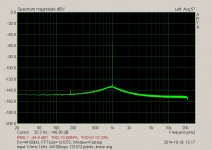
Here are some measurements for an OPA1611 in composite with TPA6120.
This is based on a design that JCX put forth a few months ago.
The first is the generator on it own. Gen output is 2.5Vrms @ 1kHz.
The signal is attenuated to 1Vrms before measurement.
ARTA set to 44.1ksps 131072 data points, linear averaging. Flattop window.
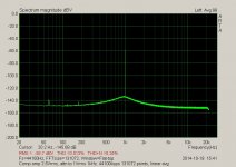
The second is the comp amp set to unity, non inverting input.
Input 2.5Vrms attenuated to 1Vrms. All else the same.
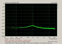
The third is the comp amp with a 200 ohm load added.
This is based on a design that JCX put forth a few months ago.
The first is the generator on it own. Gen output is 2.5Vrms @ 1kHz.
The signal is attenuated to 1Vrms before measurement.
ARTA set to 44.1ksps 131072 data points, linear averaging. Flattop window.
The second is the comp amp set to unity, non inverting input.
Input 2.5Vrms attenuated to 1Vrms. All else the same.
The third is the comp amp with a 200 ohm load added.
Attachments
Depends on how much class A load you need. The BUF634 can be set to 30mA quiescent IIRC.
That would be 20mA RMS, or 12VRMS in 600 ohms, class A.
What's your requirement?
Jan
To answer your question. 16Vrms into 50 ohms with sub -140dB THD. This will come from two amps in bridge operating as a differential output.
16Vrms into 50 ohms
Why that much? That's 5W of power from an instrumentation generator output, isn't it?
Pro audio stuff is usually spec'd at 600ohm, why not following the standards?
@ Waly -- For me, it's because you can never have enough clean power from generators. If it can work well at those levels, then I can ignore issues of loading in general. Like Grand Coulee Dam, it just won't care what you hook up to it.
With a bit work this after noon I now have this.
Better but has a ways to go.
First thing was removing the ferrite chip I put at the output. I thought this would improve decoupling but it was at a cost 1.5 orders of magnitude of distortion.
I changed the rest of the bypass caps from grounded to rail to rail The load has increased to 100 ohms. All else is the same.
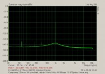
Here is the result.
Better but has a ways to go.
First thing was removing the ferrite chip I put at the output. I thought this would improve decoupling but it was at a cost 1.5 orders of magnitude of distortion.
I changed the rest of the bypass caps from grounded to rail to rail The load has increased to 100 ohms. All else is the same.
Here is the result.
Attachments
the TPA6120 is fast enough/low enough output Z that the decoupling doesn't have to happen til 10s of MHz - that allows using sub uH air coil inductor, a air coil toroid will have much less external field to couple to circuitry or chassis metal than a straight coil
still may want a few 10s of Ohms R in parallel with the coil to avoid peaking
still may want a few 10s of Ohms R in parallel with the coil to avoid peaking
the TPA6120 is fast enough/low enough output Z that the decoupling doesn't have to happen til 10s of MHz - that allows using sub uH air coil inductor, a air coil toroid will have much less external field to couple to circuitry or chassis metal than a straight coil
still may want a few 10s of Ohms R in parallel with the coil to avoid peaking
What I had in mind if it's possible is to low pass the output to 100kHz with passive components LCR.
The generator goes to 107kHz. I think the distortion will drop more putting the board in a metal enclosure. The electrolytics cans are picking up fields and driving the distortion up. I rapped them in foil and grounded the foil. That fixed the problem for now. Had to loose the shunt inductor at the TPA6120. The amp bursts into oscillation with it in. There is enough loop gain with out it.
Last edited:
50 ohms is the output impedance. It doesn't necessarily mean the amp will be loaded to 50 ohms. More likely 100 ohms or near 100. 50 ohms would be a short to ground.
600 ohms is a telecom standard. Instruments standards are either 1 Meg or 50 ohms.
For 600 ohms a 450 ohm resistor can be added in series. The 600 ohm pro audio standard I think is just carried over from many decades ago. Tube days. It began to vanish with onset of op amps. For balanced it's 600. Unbalanced is mismatched. Both are used with pro.
I don't know of very many new designs in the pro world that use a 600 ohm actual input impedance. Most of it is bridging input design, so about 10k or 20k sort of range. Occasionally you'll still find someone who runs term resistors in long lines, but that is rare anymore. (by long I mean thousands of ft. )
Mic inputs usually have a lower Z, but even that is around 1.2k reflected Z.
But as was stated, a good margin of capability makes one feel secure.
Alan Garren
Mic inputs usually have a lower Z, but even that is around 1.2k reflected Z.
But as was stated, a good margin of capability makes one feel secure.
Alan Garren
Jan it was a general comment about IC buffers. I haven't tried the BUF634.
That's why general comments are generally not valid 😉
Jan
When I tested David's prototype, I had to shield it carefully in large steel can removed from the other bench gear and computer. And battery powered it. It then measured extreamly well and clean. Afterwards, Demian Martin also tested it with similar excellent results.
A continuously variable audio freq signal generator of this high level of performance is a big deal IMO. If the amp OPS can be finalized, this will be a tremendous product !
David also has some very good ideas towards an analyzer, too.
Lets all support/help his huge effort and talent.
THx-RNMarsh
A continuously variable audio freq signal generator of this high level of performance is a big deal IMO. If the amp OPS can be finalized, this will be a tremendous product !
David also has some very good ideas towards an analyzer, too.
Lets all support/help his huge effort and talent.
THx-RNMarsh
Last edited:
When I tested David's prototype, I had to shield it carefully in large steel can removed from the other bench gear and computer. And battery powered it. It then measured extreamly well and clean. Afterwards, Demian Martin also tested it with similar excellent results.
A continuously variable audio freq signal generator of this high level of performance is a big deal IMO. If the amp OPS can be finalized, this will be a tremendous product !
David also has some very good ideas towards an analyzer, too.
Lets all support/help his huge effort and talent.
THx-RNMarsh
If you insist on 5W output power then the steel case will bite back for sure.
Yes. Definitely. However, 5W need not be insurmountable with care; In my tests ---- If the steel case is >2.5 inches from any analog circuitry etc...... and was surrounding a copper case .... as was the case with my testing.... it will be OK. In other words... a dual case.... copper first and seperated by several inches was the steel case around it all. And then there was battery power between the two cases and grounding.... all not discussed yet.
Then of course, computer floating on its battery power, analyzer plugged into 1KW Topaz Ultra-Isolation transformer and single point ground and double shielded cables. Just to make sure.
THx-RNMarsh
_______________________
you are somebody.
Then of course, computer floating on its battery power, analyzer plugged into 1KW Topaz Ultra-Isolation transformer and single point ground and double shielded cables. Just to make sure.
THx-RNMarsh
_______________________
you are somebody.
Last edited:
That's why general comments are generally not valid 😉
Jan
LOL.
I get a bit frustrated from time to time.
Yes. Definitely. However, 5W need not be insurmountable with care; In my tests ---- If the steel case is >2.5 inches from any analog circuitry etc...... and was surrounding a copper case .... as was the case with my testing.... it will be OK. In other words... a dual case.... copper first and seperated by several inches was the steel case around it all. And then there was battery power between the two cases and grounding.... all not discussed yet.
Then of course, computer floating on its battery power, analyzer plugged into 1KW Topaz Ultra-Isolation transformer and single point ground and double shielded cables. Just to make sure.
.
...and all this for the luxury of putting 25Vpeak into 50ohm. I still don't get this requirement, why not 50V then? Some tube guys would certainly appreciate that.
My Boonton 1121 will deliver 16V RMS open circuit and 8V into a 50 Ohm load and it has been very useful. Measuring frequency response with a 600 Ohm source will show the effect of the cable with even no load, its more than you would think. Also I have seen the distortion change with source impedance so its very valid to start low. Adding series impedance is not hard.
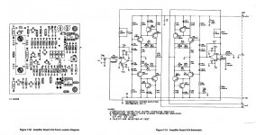
Handling the power dissipation is not trivial. The Boonton's output is bolted to a big heat sink. Also the series resistors for the output need to handle the peak power without generating distortion. I attached the output circuit for reference.
Handling the power dissipation is not trivial. The Boonton's output is bolted to a big heat sink. Also the series resistors for the output need to handle the peak power without generating distortion. I attached the output circuit for reference.
Attachments
My Boonton 1121 will deliver 16V RMS open circuit and 8V into a 50 Ohm load and it has been very useful. Measuring frequency response with a 600 Ohm source will show the effect of the cable with even no load, its more than you would think. Also I have seen the distortion change with source impedance so its very valid to start low. Adding series impedance is not hard.
Handling the power dissipation is not trivial. The Boonton's output is bolted to a big heat sink. Also the series resistors for the output need to handle the peak power without generating distortion. I attached the output circuit for reference.
Looking at the circuit will show that the output amp is a current feedback design like the TI chip.
- Home
- Design & Build
- Equipment & Tools
- Low-distortion Audio-range Oscillator