My Boonton 1121 will deliver 16V RMS open circuit and 8V into a 50 Ohm load and it has been very useful. Measuring frequency response with a 600 Ohm source will show the effect of the cable with even no load, its more than you would think. Also I have seen the distortion change with source impedance so its very valid to start low. Adding series impedance is not hard.
Handling the power dissipation is not trivial. The Boonton's output is bolted to a big heat sink. Also the series resistors for the output need to handle the peak power without generating distortion. I attached the output circuit for reference.
And who said to set the output impedance fixed to 600ohm? You can have it zero, 50ohm, 600ohm switchable. What I'm questioning is the requirement to support 50ohm loads at 25Vpeak with -140dB THD.
The Boonton 1121 residual distortions are 60dB higher than this artificially imposed requirement (spec'd at 0.01% 20Hz-20KHz, 80dB bandwidth), so the circuit you posted is three orders of magnitude worse than the target.
Handling the heat is a weak spot with the TI IC. The pad is about 1/4" square. The intention is to use the copper pour to spread the heat. I don't think this will work with continuous signal. DSL is a dynamic signal. Lot s of time for cooling.
the THS6012 version of the chip datasheet shows 3"x3" 2 oz Cu soldered PowerPAD plot with 4 W continuous @ 60 C air temp with just PCB - I think this is only using internal 1 oz gnd plane as heat spreader
details for PowerPAD analysis http://www.ti.com/lit/an/slma002g/slma002g.pdf
4 W chip power dissipation is good enough for 50 Ohms Class A at the ~ +/-14V output swing with +/- 15 V suppy
better can be done - use the backside 2 oz copper as heat spreader to a soldered SMT heat sink
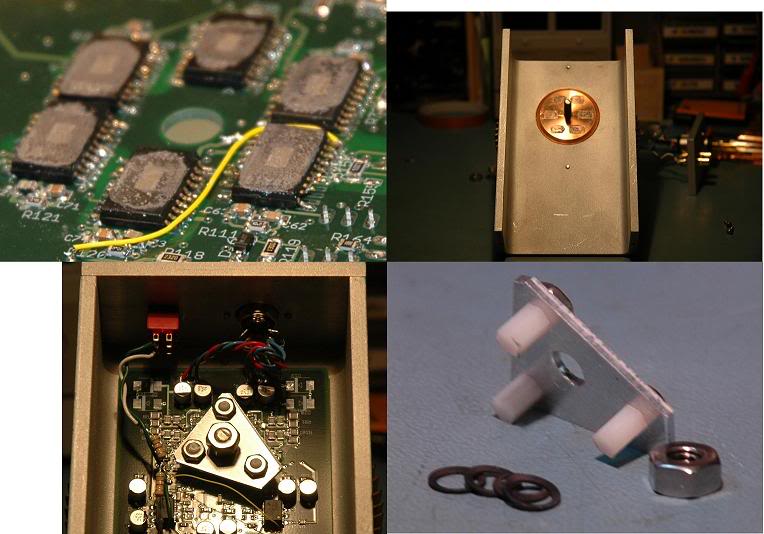
or my extreme option - mount chips belly up and clamp a CPU or Video Chip cooler to exposed PowerPAD
likely measured with copper cold plate with cooling water pipes - the specs do say: "25 C case temperature"
and probably elevated to a top line bold/bullet item by some marketing genius
once you realize the test conditions its easy to apply a factor of say 50% for what a farily good convection air cooled heatsink could do with the part
I am sucking > 6W from each TPA6120 op amp by clamping its power pad to a copper slug PC cooler:
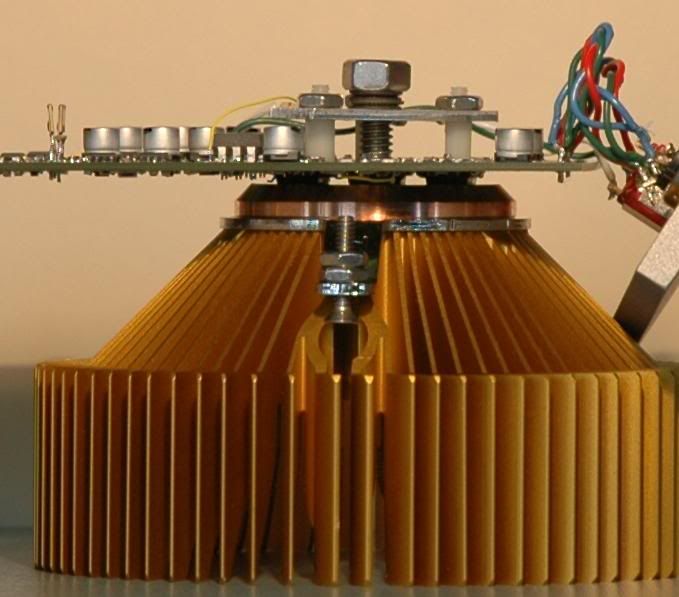
side view of 6x TPA6120 mounted "belly up" to clamp pwr pad to CPU heatsink Cu slug
internals:
Last edited:
jcx;4095486 or my extreme option - mount chips belly up and clamp a CPU or Video Chip cooler to exposed PowerPAD[/QUOTE said:I'm not sure you have met the telecom bean-counters. 😉
definitely a hobby build - you're right that few companies can afford that in competitive mass production when they can just hit spec with a fraction of the power
of course prototypes often run >10x the price expected in production - I think with pro Eagle license, pro fabbed 4 layer boards, parts in 10x qty I spent over $3k on the project even with moonlight access to my workplace' full Electronics Lab and Machine Shop
of course prototypes often run >10x the price expected in production - I think with pro Eagle license, pro fabbed 4 layer boards, parts in 10x qty I spent over $3k on the project even with moonlight access to my workplace' full Electronics Lab and Machine Shop
Last edited:
I'm not sure you have met the telecom bean-counters. 😉
Scott, please. Talking about bean-counter's; (i.e., accountants, etc.) as though
they are a derogotive (spell check can't find it) member or a special, lower class of telecom worker.
Don't loose site of the fact that bean-counter's are a fact of every day life
and not just prevalent in the telecom industry....
....think GM here, Automotive! Yeah and deaths from the auto maker being
to damn cheap to invest a few cents more for a proper ignition switch
has lead to many deaths and congressional hearings.
How many cell phones or land lines have killed people like that?
Accounts are limited by their education, training, and certification
in their profession to limit their view and understanding to only
what the numbers tell them. A good accountant can manipulate
those numbers, ever hear them?
"What do you want the numbers to say?"
Yeah right, maybe I stepped on your tail, SORRY.
...and all this for the luxury of putting 25Vpeak into 50ohm. I still don't get this requirement, why not 50V then? Some tube guys would certainly appreciate that.
I dont know.... maybe its just a 'why not'? challenge to one's self to push the existing limits. I mean, same question could be asked about 'why <-140dB'? Why not. And, right now it is hard to measure below -140 to see where the harmonics actual are. So, if you dont try, you cant do better. I know David has put in a lot of time and effort and money to find out. And has succeeded.
A couple years ago, I asked myself if I could measure -160dB. I came close - at great time and expense - at -150dB with +/- 1dB uncertainty. But I had to cheat to get there.... I finally just bought it. But, I learned an awful lot in the attempt and so was worth it all. Mostly from the shoulders of others plus getting in there and getting my own hands dirty.
This variable frequency osc/generator will cost a lot less than commercial/industrial products I spent time and money on. I hope he will write it up for publication in prof journal just for the concepts used if not in detail.
This all started because DIY'ers on a budget could design amps that we couldnt measure or afford to...... the necessity to measure -- the mother of invention.
THx-RNMarsh
Last edited:
The Boonton 1121 residual distortions are 60dB higher than this artificially imposed requirement (spec'd at 0.01% 20Hz-20KHz, 80dB bandwidth), so the circuit you posted is three orders of magnitude worse than the target.
All of mine are 30 dB better in the mid band and this is a 25 year old design. The designer is contributing changes here on DIY audio making it better. My point was about the necessary power dissipation.
The Krohn Hite 4400 has a 50 Ohm output as well but its quite current limited and in some applications has proven to be a limitation. The later 4402 has a differential 50 Ohm output that can drive to the full 7V internal or 3.5V across 50 Ohms. Using a 50 Ohm source and a straight resistive divider the source noise will be lower at pretty much any attenuation than any preamp. It will also be less sensitive to external interference.
 So, that is the reason my K-Hites have + and - outputs ! 😎
I was so focused on trying to get the distortion even lower, I just didnt think about the Why.
THx-RNMarsh
Last edited:
definitely a hobby build - you're right that few companies can afford that in competitive mass production when they can just hit spec with a fraction of the power
of course prototypes often run >10x the price expected in production - I think with pro Eagle license, pro fabbed 4 layer boards, parts in 10x qty I spent over $3k on the project even with moonlight access to my workplace' full Electronics Lab and Machine Shop
Aaahhhh another Hard-Core DIYer. 🙂
How many paralleled devices needed to get below -140 at level and Z desired?
THx-RNMarsh
Last edited:
The belly up thing is interesting. Could do a cut out on the board for the IC to sit in and bottom mount the IC belly down with the IC on the back of the board. Could press it against a heat sink this way. The IC will raise the board a bit. No via contact.
You just using some thermal paste this way?
You just using some thermal paste this way?
Yeah right, maybe I stepped on your tail, SORRY.
Maybe so, but my point was why limit your thinking to just one small
area such as telecom. Bean counters are invasive, the same everywhere.
Their affect is felt universally.
Appologie Accepted.
the buffer/CFA DSL drivers have to be used inside another great op amp feedback loop in a multiloop/composite amp to get the sum ppm performance
I like the CFA because they can have local feedback with Vgain so the input op amp isn't working as hard - and can be ran from sub regulated supplies
there aren't single op amp solutions but the composites do have the drive capability - if your layout is up to the demand
multilooped Class AB DSL drivers have the capability with the CFA alone managing -100 dB specs for few hundred mA into 25 Ohm DSL line xmfr primaries
and today's really great ~>~20 MHz input op amps giving 40 dB more distortion reducing loop gain to few hundred kHz
but supply and gnd common impedance coupling of the half wave rectified Class B portions of the load current waveforms alternating in the pos, neg rails require extreme layout care
I have repeatedly shown you can bias paralleled op amp outputs into Class A push-pull - which then should reduce PS, return nonlinear current components, easing layout
I have wrapped all the techniques together - OPA627 input looping paralleled, Class A biased TPA6120, sub regulated input supply
I find It hard to believe you can't get the required performance form such a "buffer" composite even driving few Watts into 50 Ohms - since I have
That's what I meant, basically. I thought it was plainly obvious that the BUF634 (or equivalent) was to be used inside of a feedback loop with another super awesome op amp, so I didn't think I had to explain it. I'm going to look into this TPA6120, thanks for the tip! I'm always looking for better stuff out there.
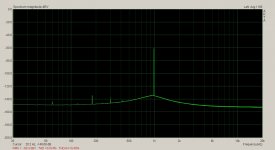
Wow. Ill say. Very well behaved and quiet. Thru a buffer, yet?
-RNM
The 10kHz needs some work though.
I'm not getting the result from using filtered rails, ( down regulated as JCX puts it), on the op amp. Distortion rises.
Here is a clear picture of the buffer's requirements.
The output Z is fifty ohms. I shouldn't have said loaded to 50ohm. The lowest load is more like 84 ohms. The oscillator won't come close to -140db At 100kHz so there no need for the buffer to this. The <-140db is between 1kHz to 10kHz of individual harmonics namely 2nd and 3rd with an absence of Harmonic above this. The bandwidth should be greater than 100kHz to maintain level flatness. Demian measured the flatness at 0.02dB through the ranges so the buffer should manage this. The distortion rises above 10kHz to < -130dB at 20kHz and the up rising curve continues from there. The distortion rises below 1kHz similarly. The buffer must be very low noise so FB components well under 1k are needed and the output drive must be able to accommodate this in addition to the the output load.
Layout, power supply and decoupling appear to be the biggest challenge at the moment.
The LME49600 should meet your specification for a buffer (to be used inside of a feedback loop with the opamp of your choice).
The LME49600 should meet your specification for a buffer (to be used inside of a feedback loop with the opamp of your choice).
Hi dirkwright,
I evaluated the LME49600. It pretty good but doesn't quite make it to the level I'm after.
Thanks for the tip though.
- Home
- Design & Build
- Equipment & Tools
- Low-distortion Audio-range Oscillator