Does anyone Know a way of getting the output current up to 1A with the Jung regulator?
As it is it's limited by the pass transistor beta to about 300mA for the the positive and 200mA for the negative. 5mA at minimum beta 60/40.
Use Darlington power series pass device?
Last edited:
Rick there is a few Twin T PCBs floating around. Wouldn't take much to assemble one and mod your B&K.
Yes, i was presented with a twin-T pcb by a generous donor and I put all the parts in it .... and there it has stayed on my work bench.
But, it is still a tempting thing to do with the B&K. I might gather up the energy/time to do that because it would be soooo cool. But, few others here would be able to get a B&K and duplicate the effort. If the 334 does not work out, then the B&K goes active will be Plan B.
Thx-RNMarsh
Last edited:
Use Darlington pass device?
I thought of that but I wasn't sure if the extra diode drop would cause an issue.
The hubble method allows for the current source to be increased but this would have be in the order of 20mA and 25mA to satisfy a 1A pass current.
Check out ghg's forum... he also had a B&K 1607 notch filter and did the active mod. Looks pretty easy and straight forward to empliment.
THX-RNMarsh
THX-RNMarsh
Last edited:
I was wondering about doing it this way when I came across this.
What is the load and what is your goal? 1A is a lot for opamps and not much for a power amp. How much noise and what output Z is required?
What is the load and what is your goal? 1A is a lot for opamps and not much for a power amp. How much noise and what output Z is required?
Hi Demian,
I won't know my final requirements until the project is compete. I don't want to come up short. There are on board shunt regulators dropping from +/-15V to +/-7V and 5V. 75mA there. The relays suck back 22mA each. One relay is normally closed so the oscillator will start up without the need to energize a relay. In any other range two relays need to be energized. The attenuator will also use relays and then there is the output amplifier and the oscillator core. The relays need a ripple free current otherwise there will be pickup of 60 and 120Hz. Micro controller and SPI expander won't use much. The SPI expander also doubles as a relay driver. Noise must be as low as possible. Output Z is not so important. There is a ton of bypassing and LP filtering of the power rails. The regulator must be able to handle capacitive loading.
I can see close to 1A.
Cheers,
Yes, i was presented with a twin-T pcb by a generous donor and I put all the parts in it .... and there it has stayed on my work bench.
But, it is still a tempting thing to do with the B&K. I might gather up the energy/time to do that because it would be soooo cool. But, few others here would be able to get a B&K and duplicate the effort. If the 334 does not work out, then the B&K goes active will be Plan B.
Thx-RNMarsh
Hi Rick,
After what Dick went through a couple of years ago. I would say the B&K would be the much easier project. As for accessibility to others something other than the 334.
Cheers,
Hi Demian,
I won't know my final requirements until the project is compete. I don't want to come up short. There are on board shunt regulators dropping from +/-15V to +/-7V and 5V. 75mA there. The relays suck back 22mA each. One relay is normally closed so the oscillator will start up without the need to energize a relay. In any other range two relays need to be energized. The attenuator will also use relays and then there is the output amplifier and the oscillator core. The relays need a ripple free current otherwise there will be pickup of 60 and 120Hz. Micro controller and SPI expander won't use much. The SPI expander also doubles as a relay driver. Noise must be as low as possible. Output Z is not so important. There is a ton of bypassing and LP filtering of the power rails. The regulator must be able to handle capacitive loading.
I can see close to 1A.
Cheers,
if you can split up the supplies and use more than one you will be way ahead. logic and relays get one supply. Its lot less noise sensitive and an lm317 should be enough. The opamps also are less sensitive if they have any PSRR to speak of. The other circuitry is more sensitive I presume but its much easier to get low noise on lower currents. Separating the supplies into several also allows much easier ground management. If the return currents don't share then they can't mess each other up. It means several transformers or windings on one transformer but the rest is easier.
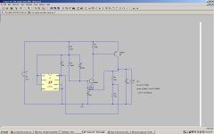
The regulator circuit I used here: http://www.diyaudio.com/forums/digi...sb-interface-audio-widget-52.html#post2810970 is for low current but a bigger pass device with current gain can handle 1A in simulations. If you have enough supply compliance a darlington pass device would work OK as well. The noise really measures as below 1nV/rtHz.
if you can split up the supplies and use more than one you will be way ahead. logic and relays get one supply. Its lot less noise sensitive and an lm317 should be enough. The opamps also are less sensitive if they have any PSRR to speak of. The other circuitry is more sensitive I presume but its much easier to get low noise on lower currents. Separating the supplies into several also allows much easier ground management. If the return currents don't share then they can't mess each other up. It means several transformers or windings on one transformer but the rest is easier.
The regulator circuit I used here: http://www.diyaudio.com/forums/digi...sb-interface-audio-widget-52.html#post2810970 is for low current but a bigger pass device with current gain can handle 1A in simulations. If you have enough supply compliance a darlington pass device would work OK as well. The noise really measures as below 1nV/rtHz.
The logic, relays etc are static most of the time. Just a steady dc current. The controller can be put into sleep mode when it not being used, then were in the low uA. Not much concern here. The ADCs on the other hand run continuously and so does the switching for them and that's where the real concern is. Samuel pointed out that on board shunt regulation running of the 15V rails is quite sufficient but it has to be shunt. Low Z is not necessary for this just a short return path.
I'll consider your regulator but I really don't like those noisy little 431s.
How did you manage to clean that up?
Cheers,
If you look at the circuit the TL431 is used as a servo with a long time constant. Its isolated from the base of the amplifying transistor by a large resistor and cap. The noise at the base is well below .1 nV/rtHz. The transistor is the dominant noise source. The TL431 steers the base voltage but slowly. The stability and accuracy of the 431 is great, especially for the price. The isolation is also good from around 10 Hz to 500 KHz.
If you have isolation (curent source) a shunt regulator for the ADC's could work. It would look like a resistor to the main supply. The bypassing and shunt regulator should be upstream from the connection to the return. If you could isolate it with a series resistor from ground then even less possibility of contamination from its noise. I presume the DAC is differential in and the output could be referenced to the target's ground making the entire subsystem isolated in effect.
If you have isolation (curent source) a shunt regulator for the ADC's could work. It would look like a resistor to the main supply. The bypassing and shunt regulator should be upstream from the connection to the return. If you could isolate it with a series resistor from ground then even less possibility of contamination from its noise. I presume the DAC is differential in and the output could be referenced to the target's ground making the entire subsystem isolated in effect.
I Haven't seen an Mdac which in differential. They are different animals compared to audio dacs. The shunts are isolated by current sources. Can't isolate ground in a mixed signal system. One just has to be careful to place noisy current hogging stuff close to the power entry and the sensitive stuff down stream and at the opposite end of the board. There's no difference between analog and digital ground with this ADC and Mdac. If the ground is split the grounds are then at different potentials.
If you have isolation (curent source) a shunt regulator for the ADC's could work. It would look like a resistor to the main supply. The bypassing and shunt regulator should be upstream from the connection to the return. If you could isolate it with a series resistor from ground then even less possibility of contamination from its noise. I presume the DAC is differential in and the output could be referenced to the target's ground making the entire subsystem isolated in effect.
Come to think of it your regulator might be just the thing. The Jung is too sensitive to capacitive loading at high frequencies. I think the pass transistor will get taken out at power up. I've seen this before with fast emitter followers. Just got to figure out how to get larger pass transistors to work with yours. Okay back to spice.
Cheers,
There has been some back and forth on C3. I get fine results with a .1 uF on the assembled units but the simulations suggest a much larger cap like 100 uF is necessary.
I have attached a zip file with the LTspice model and a 1A variation I did some time ago. Playing with the value of R3 will trade output Z for lower noise (as its also the bias current on the transistor). I am currently using the circuit with the 2.2K R3 to run all of the logic of a PCI sound card with no problems.
I have attached a zip file with the LTspice model and a 1A variation I did some time ago. Playing with the value of R3 will trade output Z for lower noise (as its also the bias current on the transistor). I am currently using the circuit with the 2.2K R3 to run all of the logic of a PCI sound card with no problems.
Attachments
Hi Demian,
I need +/-15. If I raise the voltage the 431 oscillates.
I had this happen before in the real world not just sim.
A speed up diode parallel R6 is helpful. Starts up in ms instead of seconds.
Cheers,
I need +/-15. If I raise the voltage the 431 oscillates.
I had this happen before in the real world not just sim.
A speed up diode parallel R6 is helpful. Starts up in ms instead of seconds.
Cheers,
Last edited:
This sim seems to run ok. Must have been my model of ZR431.
Attachments

Last edited:
That's probably where the 100 uF cap is important. I just scaled the sim to 15V out and 18V in. Change the following values and I don't see oscillations- R4 to 1K, C2 is .1u, voltage divider is 12.5K and 2.49k for 15V out. Load is drawing 150 mA. It seems to be pretty forgiving, which is good since I'm pretty abusive of this stuff.
That's probably where the 100 uF cap is important. I just scaled the sim to 15V out and 18V in. Change the following values and I don't see oscillations- R4 to 1K, C2 is .1u, voltage divider is 12.5K and 2.49k for 15V out. Load is drawing 150 mA. It seems to be pretty forgiving, which is good since I'm pretty abusive of this stuff.
C2 has a huge influence on the wide band output noise. Dropped from about 3uV at 0.1u to 87nV at 100u.
- Home
- Design & Build
- Equipment & Tools
- Low-distortion Audio-range Oscillator