Input protection
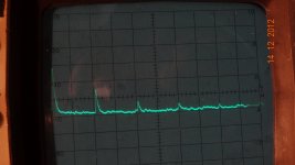
I have attached clips from three different approaches to input protection.
The Fluke 8922 is a TRMS voltmeter. They use high input Z and diode connected transistors to internal rails to limit the max voltage at the sensitive circuit. it doesn't degrade the input enough to affect its specs (.5% 50 Hz to 200 KHz) and a min input of .18 mV
The Amber 3501 has a series resistance (500 Ohms) and light bulbs plus a shunt diode to a current source to limit the max input to the sensitive stage.
The Boonton 1121 uses small fuses (1/16 A) in series with a min R of 10K and diodes tied to the internal rails to protect the input. That 10K resistor probably limits the minimum noise of the unit. it still will get to .0007 % THD with a 30 KHz bandwidth so its not a real limitation. (I can't get the oscillator down that far yet. Work to do.) It does have autoranging so the input attenuator will switch up pretty quickly.
My current take would be series fuses at a high Z node with diodes. I would much rather replace fuses than an expensive opamp.
Attachments
that one and several others as well. Whats up with these companies not being SOTA in lowest harmonic distortion attainable... and at their prices, too?? [no need to answere] -RNM
When I used the thd+noise instrument from Demian, it was reading on my little amp... .0005% . Too close to the test equip residual? The FFT output was uncalibrated so that didnt help. can it be easily/accurately calibrated? Looking for a test system to easily and accurately measure harmonics in the .00001 - .0001% area. Thx-RNMarsh
The closed loop THD only with that box (Shibasoku 725) plus the generator is around .00005 (-130 dB) or less. I have verified that its accurate. You use the individual harmonic measurement to calibrate the FFT output to known levels.
One of the big challenges, and Scott touched on it, is settling time/ frequency response from the AGC. If you can allow 30 seconds for settling it may be possible to use a lower distortion solution. All of the commercial products today are expected to sweep pretty quickly with infinitely low distortion. Something must give.
Smoking.
What version of software do you have?
.964 It thinks its in a 32 bit system. . .
.964 It thinks its in a 32 bit system. . .
It's probably compiled in win32.
Do you want to try a previous version?
I'll wait for a response from the mothership before I do much more. I'm too busy to put much time in right now anyway.
The closed loop THD only with that box (Shibasoku 725) plus the generator is around .00005 (-130 dB) or less. I have verified that its accurate. You use the individual harmonic measurement to calibrate the FFT output to known levels.
One of the big challenges, and Scott touched on it, is settling time/ frequency response from the AGC. If you can allow 30 seconds for settling it may be possible to use a lower distortion solution. All of the commercial products today are expected to sweep pretty quickly with infinitely low distortion. Something must give.
I have played - decades ago - with such long time constant oscillators.... but 30 seconds is way too long if I want to make null and balancing adjustments. The Shibasku 725 is 5-10 times better than i need so that should be accurate enough for now. Need to find another.. cant get to you often enough for any long term developemt work... just a spot measurement now and then. I'll be looking for one. Thx-RNMarsh
Shibasoku AD725D - LG
hah!! I no sooner say I'll look for one and the next second there it is on eBAY ! A nice looking AD725D. And, it ships from Calif. 😎
L.G. My present to myself. Well... it tiz the season. Now for that great FFT software I am looking for. 😀 -RNM
I'll be able to check that 339A out real good now and then some.... and get back to amps et al.
hah!! I no sooner say I'll look for one and the next second there it is on eBAY ! A nice looking AD725D. And, it ships from Calif. 😎
L.G.
My present to myself. Well... it tiz the season. Now for that great FFT software I am looking for. 😀 -RNMI'll be able to check that 339A out real good now and then some.... and get back to amps et al.
Last edited:
AP internal oscillatorThe AP 2700 is spec'ed at -112 to -115dB. I want better, unfortunately. Thx-RNMarsh
Attachments
AP internal oscillator
This looks like an LP tuning on the notch filter or an elliptic on the oscillator filter???
so thier spec is for the whole deal; source and analyzer, together, I would suppose? Or does the total sum of the harmonics shown = thier spec number? Thx. RNMarshAP internal oscillator
Richard, they specify THD+N in 22kHz bandwidth:
Analog generator residual THD+N At 1 kHz _(0.00025% + 1.0 μV) [–112 dB], 22 kHz BW
Analog analyzer Residual THD+N: At 1 kHz _(0.00025% + 1.0 μV) [–112 dB], 22 kHz BW
Analog generator residual THD+N At 1 kHz _(0.00025% + 1.0 μV) [–112 dB], 22 kHz BW
Analog analyzer Residual THD+N: At 1 kHz _(0.00025% + 1.0 μV) [–112 dB], 22 kHz BW
Yes. OK, I can see that. Then, I still need much better performance from these analyzers by one more zero. But that may not be possible? Thx-RNMarsh
Last edited:
Richard, you never made clear the frequency range of interest for you -- what resolution at what max freq. do you want to see?
I'd like to see what existing/future designs can do, so being about 20dB better would give some semblence of accuracy; So around -130/-140 thd+n over 20Khz bw. Or better. Thx-RNMarsh
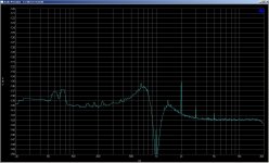
339A Residuals -
Using 339A analyzer - here is where the HP339A source residual is at (1KHz) [full scale is -80. 10dB/div]:
Using 339A analyzer - here is where the HP339A source residual is at (1KHz) [full scale is -80. 10dB/div]:
Attachments

Last edited:
Well, the EMU 0204 and the QuantAsylum 400 ADCs, used with spectrum analysis software, can both do -140dBV or better noise floors, RE 1VRMS input, out to about 30kHz, but then both show a rising slope due to the noise shaping ADCs out to the 90kHz limit, when 192kHz sampling is used.
As I've mentioned, I use an Active Twin-T filter to notch the fundamental out of the way of the ADCs. I've also used it as a front end for my Tek 7L5 with good results. The self-distortion of the Active Twin-T is unknown to me at this point, but I have reason to believe all of its products are below -135dBV RE 1VRMS input. The Twin-T has metal film resistors, wirewound pots, and polyester caps at this point.
I'm very impressed with what you and David have gotten from the 339A -- it's nice to have a single unit for source and analysis that gives dependable results, and your 2ppm result is pretty darn good. I look forward to tackling my 339 after the first of the year, tho it may be quite a while after.
Have a look at my post #772 in this thread. Using the Jim Williams super oscillator through Dick's active twin T with the HP3562A. I can see out to 100kHz with a noise floor around -135db. Also note that the oscilator output in these examples is at about 1.4vrms.I'd like to see what existing/future designs can do, so being about 20dB better would give some semblence of accuracy; So around -130/-140 thd+n over 20Khz bw. Or better. Thx-RNMarsh
Ken
Please ignore the THD values in the aforementioned post. It's calculated by an HP8903a. I usually hand calc the THD.
Last edited:
Well, the EMU 0204 and the QuantAsylum 400 ADCs, used with spectrum analysis software, can both do -140 dBV or better noise floors.
I can see out to 100 kHz with a noise floor around -135 dB.
He wants -130/-140 dB THD+N. Using large FFTs to move noise into even smaller bins doesn't help at all for THD+N...
Samuel
He wants -130/-140 dB THD+N. Using large FFTs to move noise into even smaller bins doesn't help at all for THD+N...
Samuel
Right.
- Home
- Design & Build
- Equipment & Tools
- Low-distortion Audio-range Oscillator