Why do you keep saying that, but then you don't reply to my requests of showing the test data? Is this just another scam with fake parts?
Hi mbrennwa. Not to de-rail the thread here, but Pras is legit and sells legit parts. Nelson Pass himself has bought many parts from Pras. I also have genuine Tokin THF51 from Pras with more parts on the way. I have no reason to doubt that Pras is trying to help our community get much desired rare parts at a fair price.
I have sent a message to reply to you
I have told you that I am a general measurement method, not a curve test
You asked me to write an email, which I did. I did not receive a reply. Thats why I came back here. Please post the test method and the results here so that we can judge your parts.
Because in the forum, China Network does not support uploading pictures directly
You attached some photos in your earlier post!? Also, I don't care about pictures of your parts. I am interested in the test data.
The dependence of the THD on the quiescent current. 1W/8R
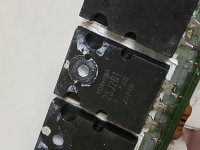
Output transistors uj3n065080k3s.
Very large 2nd harmonic Yurik. How is the sound? How did you overcome the power up issue that jpatay is experiencing?
The second harmonic level depends on the quiescent current of the output transistors. With uj3n065080k3s transistors at a quiescent current of 1A, the level of the second harmonic is -78dB is not so much.
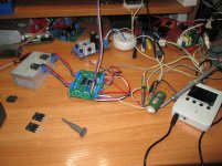
I carried out measurements on a breadboard, the power to the output stage was supplied from a laboratory power supply. Therefore, I did not have the same problem as the jpatay. 🙂
I carried out measurements on a breadboard, the power to the output stage was supplied from a laboratory power supply. Therefore, I did not have the same problem as the jpatay. 🙂
How is the sound?
I sent Yura two uj3n065080k3s to measure the harmonic spectrum.
We haven't listened to the sound yet, but Alexey wrote that the sound is as good as on 2SK1530.🙂
Last edited:
Thank you for the updates Yurik and jpatay. Great to hear the 2SK1530's sound that good. I should have mine any day now.
I gave Yura two more 2SJ162 so that he could test them in the circuit and measure the level of harmonics.
Let's wait and don't rush him.😉
Let's wait and don't rush him.😉
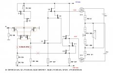
Today I tested the circuit with the inverted power supply of the preliminary part. The diagram shows the transistors that were used. At the output I used transistors IRF150, 2SJ162, 2SK1058. Quiescent current in all cases was 300mA, load 10 Ohm.
IRF150: Vout max=24V, Rout=0.38 Om
2SK1058: Vout max=20V, Rout=2.85 Om
2SK162: Vout max=18V, Rout=2.85 Om
IRF150: Vout max=24V, Rout=0.38 Om
2SK1058: Vout max=20V, Rout=2.85 Om
2SK162: Vout max=18V, Rout=2.85 Om
Attachments
By far the most stable amplifier option.
Link for ordering amplifier boards:
JFET-only Circlotrons without negative feedback v2 - Share Project - PCBWay
Link for ordering power supply boards:
Power supply unit for JFET-only Circlotron - Share Project - PCBWay
Link for ordering amplifier boards:
JFET-only Circlotrons without negative feedback v2 - Share Project - PCBWay
Link for ordering power supply boards:
Power supply unit for JFET-only Circlotron - Share Project - PCBWay
Attachments
Last edited:
I put transistors IRG4PC40U on the output. Output impedance 0.28 ohm. The maximum output voltage dropped to 13V into a 10 ohm load. When testing the meander, the output transistors went into self-heating. This was not observed with mosfet.
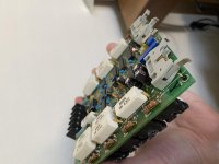
Received my 2SK1530 from Pras1170 today. Used obviously. Nice little board with 5 pairs of 1530 and 2SJ201 in good shape. Maybe some bonus components can be salvaged for tinkering too. 😉 Thanks again Pras!
Attachments

Received my 2SK1530 from Pras1170 today.
 Congratulations on your successful purchase.
I finally tamed the JFET SiC UJ3N065080K3S.
The optimal current is 400 mA. For three hours of operation, the current increases from 200 mA to 600 mA. I had to install thermal stabilization from two germanium diodes Д7Б (see circuit).
I am very pleased with the sound. High frequencies cut through. Air and volume appeared in the sound. But I had to make a delay in turning on the UJ3N065080K3S.
Rout - 0.78 Ohm. Frequency response: 5 Hz - 0.6 MHz (0 dB).
Square wave - 60 kHz.
Attachments


- Home
- Amplifiers
- Solid State
- JFET-only Circlotrons without negative feedback