I have already one SIT and bought 3 more. They will be here the next days. I will also buy the Sics to see..
Tell me 2nd stage is Voltage reg, right (Vbe)? I have already raised amplitude, I am working on the bias.
Tell me 2nd stage is Voltage reg, right (Vbe)? I have already raised amplitude, I am working on the bias.
Yes, the second stage regulates the output offset.
It is better to try the carbide scheme first.
It will be a pity to lose rare SIT from an error.
It is better to try the carbide scheme first.
It will be a pity to lose rare SIT from an error.
Which SiC parts are similar to 2SK182 and the like?Have you already bought SITs? If not, it is better to try carbides. They have characteristics close to SIT.
We have already tested such SiC Normally-On JFETs: UJ3N065025K3S (Ciss-2360pF, Ptot-441 W), UJ3N065080K3S (630 pF, 190 W). But it is better to use UJ3N065080K3S, it has a smaller capacity.
I already wrote here that you need a power-on delay on the SiC, about 2 seconds, until the gate voltage is set to -8.8 V.
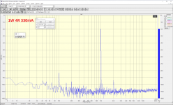
Without thermal stabilization, the current rises slowly. When the cold amplifier is turned on at currents of 150 mA, 200 mA and 350 mA for three hours, an increase in the current is visible on the diagram.
If, when you turn on the amplifier with cold radiators, set the current to 150 mA, then the thermal sensor is not needed.
I already wrote here that you need a power-on delay on the SiC, about 2 seconds, until the gate voltage is set to -8.8 V.
Without thermal stabilization, the current rises slowly. When the cold amplifier is turned on at currents of 150 mA, 200 mA and 350 mA for three hours, an increase in the current is visible on the diagram.
If, when you turn on the amplifier with cold radiators, set the current to 150 mA, then the thermal sensor is not needed.
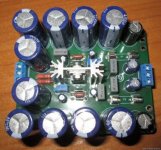
Attachments
It is very possible that carbides will be better than SIT. Their characteristic is intermediate between "pentode" and "triode". Reminiscent of the ultralinear inclusion of pentode tubes.
This mode of operation interacts better with the complex load.
This mode of operation interacts better with the complex load.
Well, it is very early to say, since I will put orders now but I will try them both. I will also use variac, so I will go carefully.
So, we need 4 power supplies for each channel? Same transformer many windings with different bridge?
So, we need 4 power supplies for each channel? Same transformer many windings with different bridge?
One transformer can only be used for Mosfet at the amplifier output.
Jfet and Sit requires two transformers. One of them is small with four windings for stabilized power supply 2x15 V, 2x30 V.
And a powerful transformer with four windings for Jfet and Sit.
Jfet and Sit requires two transformers. One of them is small with four windings for stabilized power supply 2x15 V, 2x30 V.
And a powerful transformer with four windings for Jfet and Sit.
Yes, each channel needs its own stabilizer(+15V,-30V), then there will be no background at all.
To delay the switching on of a powerful transformer, I used a simple circuit.
To delay the switching on of a powerful transformer, I used a simple circuit.
Attachments
Last edited:
Why 2x15? for stereo?
You need two such power supplies. They already have capacitors for the output stage and fuses. The PCB can be ordered in China.
Attachments
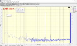
Spectrum at different load resistances. Output transistors russian KP802.
Attachments

Last edited:
impressive. In my simulations with Spice, however, I get very different type of response, mainly 3rd harmonic (with Sics not Russian).
Yes Yurik, I believe you, I am puzzled however from the difference. Anyway, the final stage is Russian, what is the front end in this plot? Russian JFETs too?
I also want to note here that in simulations, front behavior changes a lot, changing the current. 800-900 mA, 2nd harmonic lower, 900-950 2nd=3rd harmonic, 950 and more 2nd > 3rd.
Unfortunately, distortion, never goes really low. I am thinking we could enhance the front end current source, what do you think?
This is an amplifier I am definitely going to build but I want first to have the best simulation. I have changed many FETs in front and I am running many variations.
The output stage on the SIT KP802A has a large Rout = 2.5 ohms, but the sound is very good. And you can't squeeze out a lot of power on them. KP802 are very different in parameters. You need a lot of them to pick up the same parameters.
On silicon carbide Jfet Rout = 0.78 ohms and the sound is also very good.
On the IRFP150N mosfet - Rout = 0.12 Ohm and you can get the highest power. I haven't listened to the IRFP150N, but the sound might be a little worse.
You can watch the IRFP150N in the simulator.
On silicon carbide Jfet Rout = 0.78 ohms and the sound is also very good.
On the IRFP150N mosfet - Rout = 0.12 Ohm and you can get the highest power. I haven't listened to the IRFP150N, but the sound might be a little worse.
You can watch the IRFP150N in the simulator.
Last edited:
On the IRFP150N mosfet - Rout = 0.12 Ohm and you can get the highest power. I haven't listened to the IRFP150N, but the sound might be a little worse.
I would be surprised if the IRFP150 would sound worse than the SIT or SIC parts because they are essentially working as source followers only (no voltage gain). Or am I missing something?
- Home
- Amplifiers
- Solid State
- JFET-only Circlotrons without negative feedback