the circuit from the starttopic would not be hindered by common-mode stabilization of the input stage, this will be a controlled shallow NFB that will align the halves of the sinusoids to control the mosfets in the output stage,This is serious question since im beginner. I have been reading about different feedback and what they do to sound.
I used to think that negative feedback is all evil since amplifiers that use it does not generally sound too "open, flowing, organic, breathing" for me..
But then i encountered 3 amplifier, rh84 tube amplifier that uses littlebit local feedback? Threshold t200 that uses minimal feedback, and luxman l58a that uses Duobeta feedback system.:
( explanation of duobeta: https://audiokarma.org/forums/index.php?threads/luxmans-duo-beta-amps.59555/ )
All those amplifiers uses feedback and goes into catgory of "open flowing organic sound"
Otherwise, the sound will be determined by the constant selection of resistor values at the sources of the input JFets, which will need to be adjusted depending on the “weather season” outside the window and whether the neighbors’ vacuum cleaner is running.
You need to read messages No. 127, 180, 199, 200 again... We got minimal distortion at a current of 1 A. We will have to install a thermal sensor, otherwise the current will increase very slowly. The supply voltage of the output stage is sufficient at 27 V. Good luck to you.Figured I would snag a few of these while they’re readily available. I’m in between workshops right now so they’ll have to wait a few more months. But I’m very excited about the possibilities.
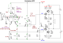
Final circuit using КП903 jfet and 1T806 germanium transistors. With a total current of 320 mA, the minimum THD was 0.051412%. Power 1 W.
When the current is increased to 400 mA, the third harmonic increases.
When the current is increased to 400 mA, the third harmonic increases.
Attachments


Thanks jpatay! I’ve been studying those posts a lot the last few weeks. I’ll be sore to post when I have some progress.You need to read messages No. 127, 180, 199, 200 again... We got minimal distortion at a current of 1 A. We will have to install a thermal sensor, otherwise the current will increase very slowly. The supply voltage of the output stage is sufficient at 27 V. Good luck to you.
It's been three years since you became interested in this topic. 🙂I’ve been studying those posts a lot the last few weeks. I’ll be sore to post when I have some progress.
I still don't understand what you meant. Could you give us a more detailed answer? Дякую. 😉the circuit from the starttopic would not be hindered by common-mode stabilization of the input stage, this will be a controlled shallow NFB that will align the halves of the sinusoids to control the mosfets in the output stage,
Otherwise, the sound will be determined by the constant selection of resistor values at the sources of the input JFets, which will need to be adjusted depending on the “weather season” outside the window and whether the neighbors’ vacuum cleaner is running.
I measured the available high-current SITs for use in a circlotron on this topic.
Each has its own graph, in the attachment is an example of number 6. Some points are summarized in a table for convenience in selecting pairs and quartets.
I chose the following quartets, in the first one it is pair 3-7, and pair 13-16.
In the second quartet, the first pair is 10-6, the second is 8-14.
Number 12 seems to be a pair of number 13, with a bias of - 4 V, and a power supply to the circlotron arms of 25 V.
But it is clearly visible that number 12 increases the current much faster when the bias and supply voltage are reduced.
The conclusion of the work is as follows:
1. It is necessary to select pairs of SITs not only by the equality of the current at one point. And also by the steepness (S).
2. For really good formation of close SIT pairs, it is necessary to record the full individual current-voltage characteristic of each transistor
It is worth noting that the SIT in this case operate in an intermediate section of the current-voltage characteristic. Intermediate between the triode and pentode.
With an almost right angle between the load line and the current-voltage characteristic line.
Similar to the UL mode of pentode tubes
With an almost right angle between the load line and the current-voltage characteristic line.
Similar to the UL mode of pentode tubes
SIT curve data from THF51, 2SJ28 and 2SK82 are available here:
https://mbrennwa.github.io/curvetracedata
https://mbrennwa.github.io/curvetracedata
Of the 19 available pcs. KP802A, the "high-current" ones with the most "left" triode characteristic were measured in detail.
3 quite satisfactory quartets were formed.
Despite the large spread not only in drain current, but also in steepness.
There were 4 "low-current" ones, and they can form not only two pairs, but also a quartet.
For this, they will need to be measured on a higher-voltage stand.
"Low-current" ones are also very valuable. Since they can be used in vacuum tube "transformer" SE instead of lamps - the maximum drain-source voltage of KP802A is half a kilovolt. In addition, they will not need a large voltage on the drain. Due to a much more complete use of the left field of the volt-ampere characteristic, unlike vacuum tube triodes.
They can also be used in the VK of the circlotron, in an already proven combination with powerful germanium transistors, for example, KP802A/GT806, KP802A/1T813.
As a result, only 3 transistors out of nineteen fell out of pairing.
If the array were larger, they would have found a pair.
Among them, number 12 stood out. With a steepness in the working zone, at a load of 8 Ohm, about 0.5 A / V. If there were several such quartets, and KP801A, B would not be needed.
Attached is a summary table for some of the measurement points. The main points located in the "corridor" of proximity to the 8 Ohm load line are colored red.
An array of measurements for all points was entered into the work log, and a volt-amps characteristic graph was immediately plotted based on them. The graph clearly showed whether the lines from the "cold" points to the "hot" points were going correctly.
"Hot" points had a spread even when measured in a fraction of a second, the graph helped to clarify the drain current value. Select the correct value.
The summary table was filled not from the work log, but according to the data of individual I-V curve graphs.
In the stand, the silicon diode was replaced with a germanium one. The voltage on it decreased from 0.6 to 0.42 V.
Which is recorded on the graphs as "+0.4".
At this voltage, there is still no forward gate current.
It shows the maximum current capabilities of the transistor when operating in field mode.
Last edited:


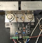
I assembled the KP1 on the KP802A and achieved excellent results. The amplifier turned out to be thermally stable. The sound is excellent. The quiescent current is 300 mA. After adjusting the quiescent current, I shorted the 0.1 Ohm resistors.
When I first turned on the amplifier, I installed 24 V/21 W car lamps instead of fuses. Now the amplifier is already working with 3.15 A fuses. Frequency response is linear 0 - 100 kHz. 768 kHz (-3 dB), 1 MHz (-6 dB). There are four toroidal transformers (one on top of the other) in the power supply.
Square wave 100 kHz:


.JPG")
Square wave 100 kHz:
Last edited:
- Home
- Amplifiers
- Solid State
- JFET-only Circlotrons without negative feedback