Well, yes, I understand the difference between SITs, SICs and conventional MOSFETs (I have read Nelsons article from your link many times). Nelson uses them in common-source configuration for current gain and voltage gain, so their voltage-gain characteristics (the "curves") are important for the sound quality.
My point is that, as far as I can tell, the Circlotron output stage has these parts configured as source followers (not common source!). The output devices therefore do not provide any voltage gain. My thinking is that the voltage-gain characteristics are therefore of little importance. That's why I expect the IRFP part to sound pretty much the same as the SIC or SIT in the Circlotron output stage.
But maybe my brain made a mistake. Let me know what you think...
"That's why I expect the IRFP part to sound pretty much the same as the SIC or SIT in the Circlotron output stage.
But maybe my brain made a mistake. Let me know what you think..."
It is very difficult to tell the difference in sound by ear. Recently I listened to a circlotron on IRFP150N with feedback, the amplifier also sounds good. Maybe I'm old and hard of hearing.
Current feedback Mosfet Circlotron
But maybe my brain made a mistake. Let me know what you think..."
It is very difficult to tell the difference in sound by ear. Recently I listened to a circlotron on IRFP150N with feedback, the amplifier also sounds good. Maybe I'm old and hard of hearing.
Current feedback Mosfet Circlotron
Last edited:
From the practical point of view, it is better to use mosfets. They have more Gfs (Forward Transconductance), which means you can get more power and less Rout. This means you can connect 4 ohm speakers.
There is a large selection of them Mosfet and they are not very expensive. There may be other benefits as well.
You just need to find suitable Mosfets.
There is a large selection of them Mosfet and they are not very expensive. There may be other benefits as well.
You just need to find suitable Mosfets.
Last edited:
Well, yes, I understand the difference between SITs, SICs and conventional MOSFETs (I have read Nelsons article from your link many times). Nelson uses them in common-source configuration for current gain and voltage gain, so their voltage-gain characteristics (the "curves") are important for the sound quality.
My point is that, as far as I can tell, the Circlotron output stage has these parts configured as source followers (not common source!). The output devices therefore do not provide any voltage gain. My thinking is that the voltage-gain characteristics are therefore of little importance. That's why I expect the IRFP part to sound pretty much the same as the SIC or SIT in the Circlotron output stage.
But maybe my brain made a mistake. Let me know what you think...
Of course there is a difference and simulations agree. It doesn't matter if it is a source follower but where the bias is, so where the VxI are on the graph of Vds <-> Is with Vgs curves. I get totally different FFT graphs, based on the final FET.
It is one month now I am running simulations to get the best result before I decide what the final scheme will be, based on availability of JFETs for the LTP stage (i have tried so many... now I am trying 489s...). I am also running some hybrid LTPs with JBTs and in simulation I get fantastic results. However, I am trying hard only with JFETs, because this schematic with only JFETs is such a simplicity beauty, which is going to be my next amplifier ( i will finish current project which is a pure class A 75W true till EoY).
To also answer your other question about 3rd dominant harmonic, under some configurations and bias level, a 2nd dominant harmonic appears!....
The beauty and nasty about this project is that under small relatively variations all the circuit changes character...
I am designing the pots to be in series with normal resistors so I can vary in smaller steps the resistance of LTP, which decides bias on final FETs....
I remind that very small variations in resistances change totally the character of this...
We noticed that as the power increases, the output impedance Rout decreases. And also with increasing current through the output stage. This is very good for 4 ohm speakers.
Of course there is a difference and simulations agree. It doesn't matter if it is a source follower but where the bias is, so where the VxI are on the graph of Vds <-> Is with Vgs curves. I get totally different FFT graphs, based on the final FET.
Well, it's no surprise that bias points may need to adjusted to fit the needs of different output devices, but my point was something else.
My view is this: the Circlotron output devices are configured as source followers, so they do not provide any voltage gain (they are just current buffers). The characteristics of the voltage gain (the "I-V curves") therefore should not matter much. So why bother with a JFETs, SICs, or other parts that have very linear curves? A normal MOSFET in source-follower configuration will work just as well. The output voltage at the Source pin will just be a 1:1 copy of the input voltage at the Gate pin and current will flow as necessary, no matter what the curves look like.
If some black-box simulation software says something else (as long as bias points are chosen within the needs of a particular MOSFET, JFET, SIC, whatever): Why? What's going on? What am I missing?
Savu, thanks for this. However, I don't understand what I see. I do not speak SPICE, and the plot has no axis labels and no legend.
What voltage did you show in the plot? Voltage across the source resistor?
What are the different curves (my guess is they correspond to different gate-source voltages, but I have no clue what voltage values)?
What voltage did you show in the plot? Voltage across the source resistor?
What are the different curves (my guess is they correspond to different gate-source voltages, but I have no clue what voltage values)?
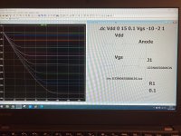
So, the info on the previous picture is as follows:
Vdd (Drain to GND) from 0 to 15Vdc in 0.1V steps
Vgs (gate to GND) from -10Vdc to -2Vdc in 1V steps.
Left is source current right is drain voltage and the curves are source current at every Vgs mentioned above.
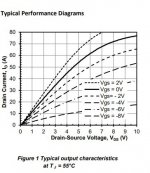
It's like this one in the attachment but instead of drain curves measurement is the source curves measurement. That's why it's upside down
Vdd (Drain to GND) from 0 to 15Vdc in 0.1V steps
Vgs (gate to GND) from -10Vdc to -2Vdc in 1V steps.
Left is source current right is drain voltage and the curves are source current at every Vgs mentioned above.
It's like this one in the attachment but instead of drain curves measurement is the source curves measurement. That's why it's upside down
Attachments
Sooo, looking at the curves in post 247, the drain current is not a linear function of the gate voltage. This means that that the voltage across the 0.1 Ohm load resistor is not a linear function of the gate voltage. Why is this so? My brain thought that a source follower is just a current buffer that copies the gate voltage to the source pin (with some DC offset). Where is he wrong?
Well it copies the voltage but because it's a V to I converter I think that the linearity of the source follower is dictated by it's transfer curves characteristics.
Thus the source current will not be perfectly linear because the jfet/tube follower is not a perfectly linear device.
If you look at emitter follower bjt output stages they (the high end designers) always pick transistors with very good linearity like the very famous 2SA1295 and 2SC3264 from Sanken. I think the reason is to keep the output stage inherited distortion down.
https://www.semicon.sanken-ele.co.jp/sk_content/2sc3264_ds_en.pdf
https://www.semicon.sanken-ele.co.jp/sk_content/2sa1295_ds_en.pdf
If you check the transfer characteristics you will notice that they are very linear in the triode region.
My view is this: the Circlotron output devices are configured as source followers, so they do not provide any voltage gain (they are just current buffers). The characteristics of the voltage gain (the "I-V curves") therefore should not matter much. So why bother with a JFETs, SICs, or other parts that have very linear curves?
Even SIT transistors are not ideal for I – V characteristics.
"Current buffers" have local feedback, which only partially linearizes the characteristics.
So the linearity of the instruments is very important.
Please note that in the technique of vacuum tubes there is a cascade of SRPP. Which has the property of greater linearity than the cascade with resistive load. And in other respects similar to it.
A very important point is the interaction of the amplifier stages, for mutual compensation of nonlinearities.
Well it copies the voltage but because it's a V to I converter I think that the linearity of the source follower is dictated by it's transfer curves characteristics.
Thus the source current will not be perfectly linear because the jfet/tube follower is not a perfectly linear device.
Even SIT transistors are not ideal for I – V characteristics.
"Current buffers" have local feedback, which only partially linearizes the characteristics.
So the linearity of the instruments is very important.
Thanks for these explanations, makes sense now.
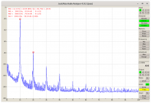
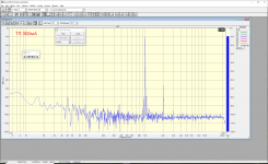
Just to convince myself I set up two circlotron output stages. One with IRFP150 MosFETs, the other with THF51 SITs (I had these parts on the bench). The harmonic distortion profiles of these two stages were always quite different. I tried different operating points, but the differences were persistent. The IRFP150 always resulted in more higher harmonics, and the THF51 always gave clearly lower 2nd. The attachments show the IRFP150 and the THF51 circlotrons biased at 24 VDC / 2 A, running at 1 W into 8 Ohm.
Attachments

The harmonic spectrum of IRFP150 and SIT KP802A, but the output stage on the SIT has a resistance 20 times higher.
The spectrum was taken from "live" amplifiers.
The spectrum was taken from "live" amplifiers.
Attachments

Last edited:
exactly mbren that's what i was talking you about from beginning, you choose the distortion you like, SIT or other FET. Also bear in mind that capacitance is different, impedance is different, they have local feedback due to small degen, so it is a different story. And again try to see, when you change the bias point ending up with serious bias current (which is what i am aiming in the end). I am in the very beginning of this amplifier, since he is in the queue as next project. I ordered all JFETs though.I also have ended design, since I have changed things to have more power (at least in simulation).
And a comment for your saying that SPICE is a black box. If you feed it with good data and gets you great approximations. All my projects were really close to spice results but I was paying very close attention to spice models.
And a comment for your saying that SPICE is a black box. If you feed it with good data and gets you great approximations. All my projects were really close to spice results but I was paying very close attention to spice models.
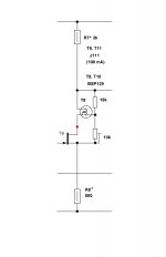
To increase the amplifier power, it is necessary to switch the buffer to the amplification mode.
You can look at such a buffer stage in LTspice, but the parameters of the amplifier may deteriorate. I do not know how to work with LTspice. The Drain-Source voltage of J111 should be 3 ... 3.5 V.
You can look at such a buffer stage in LTspice, but the parameters of the amplifier may deteriorate. I do not know how to work with LTspice. The Drain-Source voltage of J111 should be 3 ... 3.5 V.
Attachments
Last edited:
@jpatay, no worries, i have finished the design in Spice, with Toshiba FETs. I get 6Ap on 8 Ohms, using Sics, 5Ap using SITs. I ordered some genuine JFETs and now I am waiting (I have already SITs and SICs). I estimate the project to be finished in 2-3 months...
Any low-power n-channel transistor with an initial current of 5-20 mA is suitable as VT1, and as VT2 with an initial current of 1.5--5 mA.
- Home
- Amplifiers
- Solid State
- JFET-only Circlotrons without negative feedback