Because one opto-coupler is triggered when a positive voltage appears at the output, and the second - a negative one.
OK but why using two opto on this one ?
One PC817 operates at positive voltage, and the other at negative voltage.
OK !!! I had not seen the single diode instead of two thanks
yes of course a darlington on the real circuit, i just want to sim the response time and sensitivity
yes of course a darlington on the real circuit, i just want to sim the response time and sensitivity
For reliable operation of the protection, you need to reduce the resistors 22 kOhm and 56 kOhm.
You can further increase C1 to 20 μF.
You can further increase C1 to 20 μF.
Last edited:

Hello for stereo setup, two channels.
for the non high power rails, we can use the same PCB with common supply? I.e. connect both channels to same supply board?
We can do the same for the high power rails for each channel, or we have to have 4 separate rails for high power?
for the non high power rails, we can use the same PCB with common supply? I.e. connect both channels to same supply board?
We can do the same for the high power rails for each channel, or we have to have 4 separate rails for high power?
The stabilized power supply can be one for two channels.
But it is better to have a separate stabilized power supply for each channel. Then there will be no background at all.
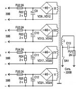
Yes, the output stages require 4 separate power supplies. One power supply is designed for one powerful transistor.
But it is better to have a separate stabilized power supply for each channel. Then there will be no background at all.
Yes, the output stages require 4 separate power supplies. One power supply is designed for one powerful transistor.
For the output stage Mosfet:
Interesting. No stabilization eh? Only one capacitor? No humming, buzzing or something?
By the way, if we have small differences in voltage, wouldn't mean that some (minor) current would flow between the output FETs? Have you measured that?
I have received all JFETs. I have also designed a new PCB and a new stabilized PSU PCB (I like to build my own PCBs). PCB for amplifier has arrived, PCB for PSU will be ordered.
I am now wondering about the output stage. I have already a high power stabilized PSU (more than 10A) from another project and works great. But it will be huge to build it 4 times. I may try something in the middle, I ll design something.
No need for stabilization output stage. There is also stabilization of the preliminary stage.
No noise is heard in the speakers. If you are using one power supply for the two pre-channels, then a slight buzzing sound may be generated.
The difference in the voltage value of the output stage is permissible, but if the voltage is high, then the Mosfets will heat up more.
One diode bridge needs 10,000 uF. I am waiting for the result of the amplifier assembly. Write about your work results. 🙂
Last edited:
I am now wondering about the output stage.
Output stage on P-channel Mosfet. (Example).
Attachments
Very nice jpatay, you have dome wonderful work. I might try germaniums at some point too
I am progressing too.
- Ordered power toroidal transformers
- Ordered some missing passive parts.
- Had designed new PSU and amp design and relevant PCBs arrived and started soldering
- Chassis from modushop ordered, waiting to finish re-anodization and send them.
I have work in front of me and I have not the luxury of time but I work a small bit every day.
Fortunately previous project is almost completed but I have so many more coming.... but after circlotron.
- Home
- Amplifiers
- Solid State
- JFET-only Circlotrons without negative feedback