Sorry, but we need JFET.
mosfet could be used for for input too, look the last schematic with mosfet input on my thread
You just need to protect the input with zener
Significant difference. No less than in the powerful variants. Because technology is the same.
In my amp they worked the same as 2SK170.
An externally hosted image should be here but it was not working when we last tested it.
SIC JFet model moded for températures
https://www.diyaudio.com/forums/sof...wer-mosfet-models-ltspice-30.html#post6169519
https://www.diyaudio.com/forums/sof...wer-mosfet-models-ltspice-30.html#post6169519
SIC JFet model moded for températures
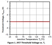
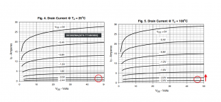
A typical
UnitedSiC JFET has a threshold or “Gate cutoff Voltage” of -6 Volts. In Figure 1, The threshold Voltage is stable
across temperature. This stability simplifies gate drive analysis with respect to a standard silicon device would have
a 2 Volt swing over the equivalent temperature range.
Attachments
So he used UJ3N065025K3S or UJ3N065080K3S ?
https://www.mouser.fr/datasheet/2/827/DS_UJ3N065025K3S-1530382.pdf 2360pF CIS
https://www.mouser.fr/datasheet/2/827/DS_UJ3N065080K3S-1530401.pdf 630pf CIS
not same device ...
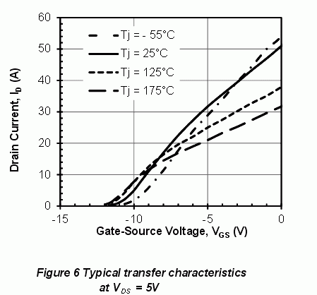
and the figure who interest me is this one :
https://www.mouser.fr/datasheet/2/827/DS_UJ3N065025K3S-1530382.pdf 2360pF CIS
https://www.mouser.fr/datasheet/2/827/DS_UJ3N065080K3S-1530401.pdf 630pf CIS
not same device ...
and the figure who interest me is this one :
Last edited:
So he used UJ3N065025K3S or UJ3N065080K3S ?
Used was a transistor UJ3N065025K3S (441W).
But it is better to use UJ3N065080K3S (190W).
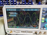
The output stage current is very stable. At 240 mA, on the gate is -9.5 V (measured relative to ground).
Rout - 0,12 Ohm.
Last edited:
Littlefuse/IXYS IXTH16N10D2. Depletion mode MOSFET, available at Mouser. Opinions, anyone?
Datasheet: https://www.mouser.de/datasheet/2/240/Littelfuse_Discrete_MOSFETs_N-Channel_Depletion_Mo-1652654.pdf
Edit: Similar parts have been used here: Firstwatt De-Lite Amplifier
Datasheet: https://www.mouser.de/datasheet/2/240/Littelfuse_Discrete_MOSFETs_N-Channel_Depletion_Mo-1652654.pdf
Edit: Similar parts have been used here: Firstwatt De-Lite Amplifier
Attachments
Last edited:
Too current transistor.
Therefore, the thermal stability point at a large current index.
It seems so.
That the depletion mode is good.
Therefore, the thermal stability point at a large current index.
It seems so.
That the depletion mode is good.
Attachments
Last edited:
Thank you. Yes, these seem to have a positive temperature coefficient all the way up.
To anyone interested in thermal stability problems of FETs, further reading in this paper: Semiconductor' '&' 'System' 'Solutions - Infineon Technologies
To anyone interested in thermal stability problems of FETs, further reading in this paper: Semiconductor' '&' 'System' 'Solutions - Infineon Technologies
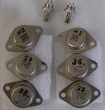
Measured its stock SIT-JFET KP802A (КП802А).
A total of 114 pieces, 87-92 production years.
Thanks, Svjatoslav!!! Today I received a package from you. Even on KP802 I can listen to the sound of Circlotron.
Attachments
Alexey Semin got good results on 2SK1058 laterals.
And if I try on P-channel laterals 2SJ162? I only need to change the polarity of the supply voltage at the output stage?
And if I try on P-channel laterals 2SJ162? I only need to change the polarity of the supply voltage at the output stage?
Attachments

Selection of appropriate transistors to service the first stage of the circuit.
It is seen that there is not enough information on the initial current.
Requires source-gate voltage at operating current.
The second attachment shows the properties of KR504NT1 and KR504NT2.
There is information about the voltage they need for the source - drain (green ring).
It is seen that there is not enough information on the initial current.
Requires source-gate voltage at operating current.
The second attachment shows the properties of KR504NT1 and KR504NT2.
There is information about the voltage they need for the source - drain (green ring).
Attachments


I conducted such an experiment. I used the N-channel jfet in the differential input, and the P-channel in the driver. The transistors were used in SOT-23 (MMBFJxxx) packages.
As a result, the MOSFET received an amplitude of ~ 14 V at the gates (5 Volts more than in the first circuit).
The transistor current is indicated in brackets:
Idss Zero-Gate Voltage Drain Current. For example: J202 - 2 mA.
As a result, the MOSFET received an amplitude of ~ 14 V at the gates (5 Volts more than in the first circuit).
The transistor current is indicated in brackets:
Idss Zero-Gate Voltage Drain Current. For example: J202 - 2 mA.
Attachments
Power supply PCBs available for customer order:
Power supply unit for JFET-only Circlotron - Share Project - PCBWay
Power supply unit for JFET-only Circlotron - Share Project - PCBWay
Hi do you think this amplifier could be used with lateral mosfet ?
I have 4 exicon ECW20N20-S
Seb, try to put 100-200 Ohm resistors into the 2SK1058 gate.
But it's better to put ECW20N20-S.
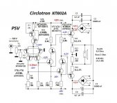
I just posted in an older thread but I see there have been some updates here. Very interested in trying the United SiC Jfet version of this amp. A question on the TO-92 jfets used. I would assume 2sj103 can be substituted with 2SK170? Does the grade matter, GR vs. BL? And 2sk246 can be 2sj74? Also, is there matching between any of the components?
Hi jwjarch, look at the circuit for possible replacement of transistors, but everything must be checked in practice. We have simplified the scheme a little. The buffer is already on two transistors. It is advisable to use transistors with a maximum voltage of 30-50 V.
Attachments
- Home
- Amplifiers
- Solid State
- JFET-only Circlotrons without negative feedback