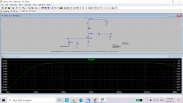
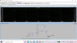
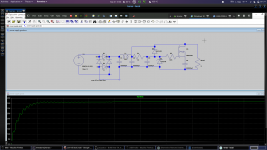
Another factor to consider is the output impedance of your preamp (modeled as series resistance of the input signal in the simulation) that will feed the amplifier. High preamp output impedance will affect the high frequency response of the amplifier.
If the output impedance of your preamp is too high, you can add a buffer at the front of the amplifier.
Simulations with 100R, 1K, and 10K impedance:
If the output impedance of your preamp is too high, you can add a buffer at the front of the amplifier.
Simulations with 100R, 1K, and 10K impedance:
Attachments

My preamp is this one:
Pre-Amplifier
I also have the exact schema and values of the crossover of the Maggies. I ll put them on the picture to see what will be the impact.
Pre-Amplifier
I also have the exact schema and values of the crossover of the Maggies. I ll put them on the picture to see what will be the impact.

190W? Tj is 125degC even if you can keep the case 50degC. I'm skeptical about dissipation, but please try it with your liquid cooling device.
The problem will be the case to heatsink thermal resistance. The liquid would need to be very cold to get enough heat from the case to the cooling device.
Ehm, I also found and ordered 2SK182ES... 🙂 Just for next versions playing with SIT. Anyone has LTSpice definition?
Did you try paralleling devices? That may work.
lhquam's Spice model is close to my Tokins from Mr. Watanabe.
lhquam's Spice model is close to my Tokins from Mr. Watanabe.
Damn coronavirus... Both my orders for 193V and SIT were calcelled and got refund.... Japan won't send to Greece. I ordered now 193V from Italy....
You probably may ask to Mr. Watanabe to ship them via Fedex or DHL. It took 2 months from Japan to US via surface mail service.
Thanx plasnu, good idea, just asked him, see what happens.
Man I am waiting too long for the parts... Still have no view for my FETs...
Man I am waiting too long for the parts... Still have no view for my FETs...
Many diyAudio members have bought genuine and tested SITs from from pras1170:
TOKIN old used 2SK180 SIT FET Power Sit Static Induction Transistor 600V 20A 300W
TOKIN old used 2SK180 SIT FET Power Sit Static Induction Transistor 600V 20A 300W
Japan answered no, so it is China for next order.
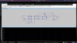
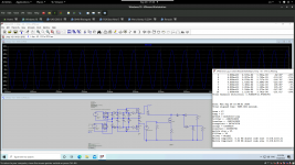
Question. I am trying to simulate the PSU from Zen 5 and when I use the topology as it is it doesn't work. When I change to 2nd scheme it works. Anyone knows what is going on? (ok it is half the PSU, only the positive, shouldn't have any issue right?)
Question. I am trying to simulate the PSU from Zen 5 and when I use the topology as it is it doesn't work. When I change to 2nd scheme it works. Anyone knows what is going on? (ok it is half the PSU, only the positive, shouldn't have any issue right?)
Attachments
Are you questioning NP's design? 😱
In your first scheme, it looks like the Rload connection to Mosfet source is faulty - there is no connection. It looks like you attempted to connect to the "body" of the Mosfet.
Once you get it running, I think you will find that you are trying to drop too much voltage with R1 at 1K. The output voltage should be about 25V - 4V = 21V or so. The current through R1 and subsequently D6 will be too high in order to get the output voltage to 21V. R1 can be increased to decrease the current.
In your second scheme the Mosfet is not regulating voltage. I believe it is doing nothing. The Mosfet is parallel to the Rload, but with C4 in series with the Mosfet, DC does not pass through so it does not affect the circuit. The C4 probably prevents the Mosfet from burning up. I think in effect you have a CLC supply supplying power to Rload.
You are right it was the connection, though it made contact but not.
Now it works but for 60V input transformer on my load I get 21V? Is this correct?
Never mind had forgot to change the zener, now drops to 40+ V. Seems impressive to me
Now it works but for 60V input transformer on my load I get 21V? Is this correct?
Never mind had forgot to change the zener, now drops to 40+ V. Seems impressive to me
Last edited:
The model with the PSU takes a couple of hours to calculate. Anyway, it is impressive how much is the voltage drop, I guess this is what CCS tries to beat right? However in the end, with some increase in distortion, it gives results.
Ordered 180ES from China, aliexpress from our friend, too. Put it on the same circuit and LTSpice says it works, weird. I would expect to have to have much different settings. Anyway, when I have them will try them.
All my orders from China, are in still in nowhere, for my other projects too, its been almost a month....
Weird thing is I have still have no news for my IXYS FETs from Germany...
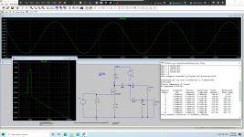
I have ended up in the below scheme, which seems to give me 1.9% thd with 30 Vp @1KHz. I am a little worried if I have the ground correctly or what. Simulation though runs like a kitten.
IXYS FET finally arrived but 193V hasn't been posted yet (finally bought from Italy). For PSU capacitors I found some huge 33mF. For output I ll try 3300uF and 33mF
IXYS FET finally arrived but 193V hasn't been posted yet (finally bought from Italy). For PSU capacitors I found some huge 33mF. For output I ll try 3300uF and 33mF
Attachments
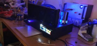
Started building PSU. At start when connected to power fuse of house went down. I added CL60 thermistor and then was ok. I added the bridges and when connect the two bridges together fuse of PSU is blown (4A). Any1 can help me?
Never mind, wrong schema, since i have middle take from transformer so i have to use only one bridge
- Home
- Amplifiers
- Pass Labs
- Inductor Loaded De-Lite