OK gave +44V, Id is 1.5A, temp of FET is 37.
I have +44V on output... Shouldn't the capacitor remove that? What is the polarity of the capacitor? + towards the speaker?
I have +44V on output... Shouldn't the capacitor remove that? What is the polarity of the capacitor? + towards the speaker?
Yes, most certainly. Connect a few kohm from cap to ground and check for DC again. You should see a few mV only.
With the resistor I got 32V. Reversed polarity and now I have 2V that changes downlwards slowly. Final capacitor is 33mF. Put a speaker on, no hum or something, complete silence, didn't measure with speaker on (forgot)
I tested 95V, we go to 50 C, I let it for 5 min.
I managed to burn my 1st FET. It happened during power off. I believe it is because the FET is still too hot and cooling shutdowns immediately. I must find a way to cut the cooling later than amplifier.
I will try from Monday again.
Where is zenmod to say its fugly?

I thought the three options, 193V, resistors and bulbs. I decided to start with inductor. I don't think bulb fits the project and I cannot find 110V bulbs here. In emulation in LTSpice works fine, so let us what happens
Duh, this is what happens when you are a n00b like me 🙂
I have some questions...
- On PSU one of the two IRFPs are getting very hot, I have a minimal heatsink, is this correct? i need to put a big one?
- I have large capacitors 33mF in PSU. Is it better to use many smaller ones?
And some pics more..
I have some questions...
- On PSU one of the two IRFPs are getting very hot, I have a minimal heatsink, is this correct? i need to put a big one?
- I have large capacitors 33mF in PSU. Is it better to use many smaller ones?
And some pics more..
Attachments
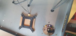

The bias supply current draw is low so that Mosfet power dissipation is low. However the Mosfet in the supply for the Iq of the amplifier output device is dissipating V x Iq, so it needs appropriate heatsinking.
Duh, this is what happens when you are a n00b like me 🙂
I have some questions...
- On PSU one of the two IRFPs are getting very hot, I have a minimal heatsink, is this correct? i need to put a big one?
- I have large capacitors 33mF in PSU. Is it better to use many smaller ones?
And some pics more..
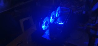
first one (blue) is porn worthy
keep them coming

Today I am more excited... Tried the "full" power version, which on simulation gives 36Vp out on 4 Ohm with 2Vin, with Rsource 0.5 Ohms. 100V V from PSU.
Measured 3A on 193V, which was cool and fine.
Water cooling started working 🙂 I touched one tube and was hot. Temp of FET 66 C with low speed of fans, 50 C with full speed.Is this a good temp?
Low speed is quiet enough, I can't hear them from 2-3 meters.
Voltage from ground to source of FET 2V. Rsource gets really hot, I put two 1 Ohm in parallel 15W each.
I let the system for one hour working. 0V on output terminals. I put a test speaker and I put my ear on the tweeter. Nothing. absolute silence.
I also burnt one FET, tested if it was what i was suspecting happened last time. If i turn power off, without the cooling working for some seconds more, the FET fries. I think I have to put some kind of delay there, or for now put two different switches.
When you turn the power off, the collapsing magnetic field in the inductor will produce a negative voltage spike. I don't know how high the negative voltage will get, but it is worth investigating, especially with 100V at 3A.
I assume you are burning your output Mosfet? What is it? What is your schematic? I assumed you were using a bias supply but it seems that you are using a source resistor.
If you are running the Mosfet at 95V and 3A, or is it 4A since 2V across 0.5R source resistor, you are asking the Mosfet to dissipate 285W or 380W. This is probably way outside the SOA of the Mosfet.
If you are running the Mosfet at 95V and 3A, or is it 4A since 2V across 0.5R source resistor, you are asking the Mosfet to dissipate 285W or 380W. This is probably way outside the SOA of the Mosfet.
schematic in post #97.
@pinholer. I am pretty sure it is because the FET is too hot and suddenly pump stops cooling and obviously the effect you are referring makes things worse. There is no heatsink to take away the remaining heat. If I leave the cooling system for some seconds there is no issue. Tomorrow I ll add a second switch so I can keep the cooling on even if the main power is off. I have also ordered delay circuits, which I am going to use for PSU and in amplifier too.
I don't have a bias circuit, only a source resistor, 0.5 Ohm. The 2V are at edges of this resistor. So it should consume V*V/R or 8W. I had one of 15W but it was getting very hot, so I put two 15W in parallel, it is much better now.
Ben you are right, if 2V then Id is 4A. I am not very sure about accuracy of my multimeter, since the "good" one was measuring temperature. On analysis with LTSpice I remember Id was 5 Ap.
I also added fans on heatsink of FETs of PSU (IRFP 250), maybe I will put one pair more, now it has a pair, one for positive and one for negative. I have some small heatsinks for now, I have ordered bigger and maybe in the end pout them on the chassis, now are on the air. With fans working, I could touch for some seconds the heatsink.
I have put 120mF total for now, it will go to 200 mF approx when my coils arrive.
I know about the 300W+ that's why I am using the liquid cooler, which to be honest seems to do a great job. I let the system more than an hour running and seems very stable. Ambient temp was 29 C and when I have fans in full speed FET goes to 44 C in the end. I hope when it is working speakers consume some of this 🙂
I am also thinking to change the FET to IXTH16N50D2 which is a 16A device, the one I am using is a 6A.
I have also ordered big EXICONs and 2SK182ES whixh are on the wayto test them too (of course with different bias)
Last edited:
....I managed to burn my 1st FET. It happened during power off. I believe it is because ...
Go ask in the MoFo thread in this section. Choke-loaded MOSFET followers can have a large inductive kick if power is disconnected suddenly. A Zener G-S is better, but maybe not proof against all events.
Would it be better to replace the inductor with a light bulb?
I may be missing a joke. The inductor will kick-up above the supply rail for potentially double the output voltage. A light bulb (resistor) won't.
I know, i know, i have read everything I could in this excellent site but as I said it was not practical the bulb, so I will try the 193V. If I fail then I will see what I will do, I have explored some options here with other types of lamp (220V unfortunately) with very big power.
Joke: Zen Mod said that the picture was too dark, so Pinholer said replace the choke with a light bulb. 
Looking at the schematic in post #97, it is very low resolution. I can see that you are floating a bipolar supply. Is that to limit the transformer and capacitor voltages instead of using a single V supply with higher transformer and capacitor voltages?
Your simulation took 9489 seconds (2.63 hours) to run. I would think that there is something wrong with your model.
You said your PS devices are IRFP250. What is your amplifier output device? Also it is not clear which device burned up. Was it the output device or the PS device?
- Home
- Amplifiers
- Pass Labs
- Inductor Loaded De-Lite