Hihttps://www.hifistor.com/index.php/shop/
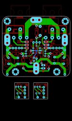
Blue board hiraga 8 watts
Is it possible to use the Hifistor boards with the original transistors without any changes, if I find any?
If I replace the 47k resistor at the amplifier input by another 50k resistor (in fact, I'm thinking of using 2 x 100k resistors, with a tolerance of 0.05%, in parallel), this would cause some damage or significant change in the amplifier's parameters. ?
I read on some forum that the input resistors (1k2 and 47k) should have the smallest tolerance possible to preserve the integrity of the input signal as much as possible, so I bought Caddock 1k2 0.01% and TE Connectivity 100K 0.05% ( 2 in parallel) to replace the originals.
But I'll only find out the result when I finish my assembly, which will take a long time...
Thank you guys!
Nilton
You can use the Hifistor boards, but I suggest to respect the resistor original values.
I have used z-foil resistors in my Hiraga amplifier. They are very expensive but it was worth it.
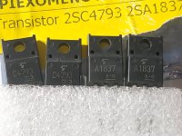
If you are planning to use that board, pay attention to the small transistors pinouts!
I have used z-foil resistors in my Hiraga amplifier. They are very expensive but it was worth it.
If you are planning to use that board, pay attention to the small transistors pinouts!
Last edited:
2x 100k 0.05% in parallel is 50k 0.035%.I read on some forum that the input resistors (1k2 and 47k) should have the smallest tolerance possible to preserve the integrity of the input signal as much as possible, so I bought Caddock 1k2 0.01% and TE Connectivity 100K 0.05% ( 2 in parallel) to replace the originals.
Which is something like 6% with respect to 47k, not ?
Not quite smallest tolerance possible ?
to preserve the integrity of the input signal as much as possible,
Can you enlighten us how a say 0.01% resistor will preserve the input signal better than say 1% ?
Thanks in advance,
Patrick
Last edited:

Respect the resistor original valuesHi
Is it possible to use the Hifistor boards with the original transistors without any changes, if I find any?
If I replace the 47k resistor at the amplifier input by another 50k resistor (in fact, I'm thinking of using 2 x 100k resistors, with a tolerance of 0.05%, in parallel), this would cause some damage or significant change in the amplifier's parameters. ?
I read on some forum that the input resistors (1k2 and 47k) should have the smallest tolerance possible to preserve the integrity of the input signal as much as possible, so I bought Caddock 1k2 0.01% and TE Connectivity 100K 0.05% ( 2 in parallel) to replace the originals.
But I'll only find out the result when I finish my assembly, which will take a long time...
Thank you guys!
Nilton
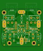

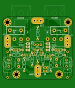
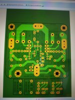
Here the original Hiraga layout.
Copied from his article and converted to Gerber.

www.diyaudio.com/community/threads/hiraga-le-monstre-2024.413301/post-7696593
Cheers,
Patrick
Copied from his article and converted to Gerber.
www.diyaudio.com/community/threads/hiraga-le-monstre-2024.413301/post-7696593
Cheers,
Patrick
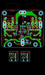
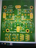
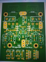
Nice layout!Hi my friends
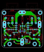
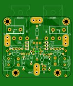
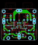
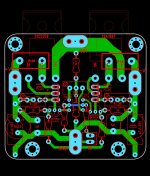
here my pcb Hiraga 8W untested....
Hi ,...after good check .
Dimensions are 56mm x 50mm
I haven't read many posts about this amplifier.
Could someone please let me know what about the bias ?
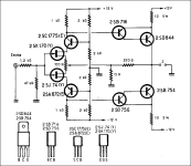
Has anyone built the schematic below?
and what combination of transistors can we use?
Dimensions are 56mm x 50mm
I haven't read many posts about this amplifier.
Could someone please let me know what about the bias ?
Has anyone built the schematic below?
and what combination of transistors can we use?
Attachments
Last edited:
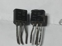
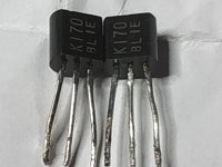
Hello Nikos, bias should be between 500 and 600mA. That will be a challenge if you use 2SK170 / 2SJ74 in the BL range, range y ist not realy existent, but GR is available and should be used. Matched to a IDSS as low as possible, if you manage to be around IDSS 3mA the 1k R has to be reduced to about 750R. Better to read a lot about this little amp, very good but there are some challenges while building.
Many users have a bias of 1A and more, the sound is not to my liking.
Many users have a bias of 1A and more, the sound is not to my liking.
Hi thanks for your responce.That will be a challenge if you use 2SK170 / 2SJ74 in the BL range, range y ist not realy existent, but GR is available and should be used.
it will be a challenge due to high IDSS ? My fets idss = 7.4ma 2sj74 and 2sk170 9.6ma
Would you like to be more specific?there are some challenges while building.
Last edited:
Understand .....so in my case with fets BL idss 7-9ma must change the two resistors 1ΚΩ to lower value 470Ω?VR100 is only to balance out the offset.
R3 / R4 need to be changed to alter bias. Higher value means higher bias. Take a higher value for the potentiometer across R3/R4.
J1 and J2 should be selected for same IDSS, Original Monster has FETs grade y with IDSS of about 2.4 mA (9 V), but nobody has seen grade since 40 years. I use grade GR around 3.6 mA and R3/R4 around 750 ohm for bias 0.6 A, that means about 900 ohm for 1 A bias (only roughly estimated values)
Last edited:
Hello Nikos,
I don't like to me unfriendly but all of this is already writen several times in this thread, not only by me but also by others, just scroll 2 pages back.
IDDS of your Fets are not only way to high but also not matched, this will end in an offset, maybe you can compensate with the pot of 100R. But this pot does't alter the bias, only offset.
If you have problems with the Fets (to find some) please contact me by PM
Sometimes the amp oscillates, this may be solved with 47 nF over 200R fedback.
It's highly advisable to read this thread, there are so many information to avoid frustration by building this nice little amp.
2x 100k 0.05% in parallel is 50k 0.035%.
Which is something like 6% with respect to 47k, not ?
Not quite smallest tolerance possible ?
Yes, it makes sense.
Can you enlighten us how a say 0.01% resistor will preserve the input signal better than say 1% ?
Well, I don't know if it is, Im here to know if it is... Technically I understand that the signal will be more linear, but if at that level it can be perceived by the ear, that's what I would like to know
Member AdrianL uses ZFoil resistors and like it, could it be due its tolerance, or due to the type of material used in its construction?
Tks
Nilton
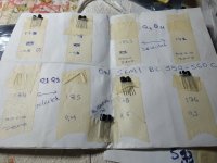
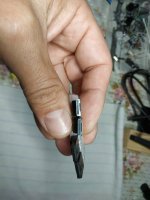
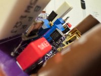
Yes I did use z-foil resistor. You can see them in the picture attached.
The difference is in sound quality. It is more precise and more detailed. Of course, this is not only the advantage of using Z-foil resistor. You must also use the other components as close to the original as possible. And make sure they are the original.
The difference is in sound quality. It is more precise and more detailed. Of course, this is not only the advantage of using Z-foil resistor. You must also use the other components as close to the original as possible. And make sure they are the original.
Attachments
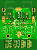
My version of the 8W LeMonstre (based on the layout from JimsAudio)

- Home
- Amplifiers
- Solid State
- Hiraga "Le Monstre"