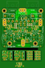
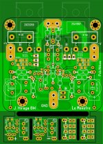
And just for fun, here is a draft of my version of "Le Monstre", heavily inspired by the dieter12's version 🙂 It is more than likely that I will never build this amp.


If anybody is interesting, I can provide the Gerbers and PCBs.
carlsor
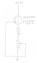
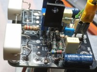
First picThe 2SK208 JFETS require much less source resistance. I used a 470ohm fixed resistor and 500 ohm pot for the “O” types I tested. A forum friend reported that 308 total ohms provided the desired 0.40 ma for his “R” types that measured an Idss of 0.60-0.63 ma.
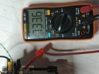
Sec pic
https://mrevil.asvachin.com/
Junction FETs are naturally suited to making current sources; just connect the source to the gate, and magically a constant current flows between source and drain over a wide range of voltages. Commercially available "constant current diodes" are a simple JFET connected like that. Connecting a resistor between source and gate reduces the current, and if it's variable then so can the current be varied, which is just what is needed here. Furthermore, I added a second JFET to cascode the current source. This increases the output impedance and improves high-frequency performance.
The particular JFETs used here are just ones I happened to have lying around, not necessarily the best possible choices. The cascode JFET must have a higher Idss than the current source JFET in order for it to remain biased on at all output currents. With the transistors and potentiometer value used here, output current can be varied from about 0.5-3.0mA.
Attachments

2SK208Υ Jfet
IDSS classification R: 0.30 to 0.75 mA, O: 0.60 to 1.40 mA, Y: 1.2 to 3.0 mA, GR: 2.6 to 6.5 mA
IDSS classification R: 0.30 to 0.75 mA, O: 0.60 to 1.40 mA, Y: 1.2 to 3.0 mA, GR: 2.6 to 6.5 mA


Here's some news. It's about upgrading my existing Le Monstre. I'll open a new topic about it soon.
Attachments

Hello,
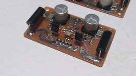
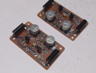
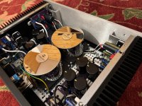
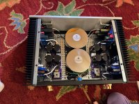
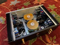
This is my latest Hiraga Le Monstre built.
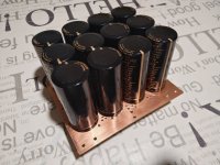
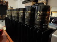
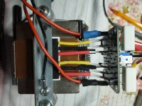
In the CRC filtre I have used 8 Mundorf M-Lityc Audio grade capacitors of 47000uF each.
This is my latest Hiraga Le Monstre built.
In the CRC filtre I have used 8 Mundorf M-Lityc Audio grade capacitors of 47000uF each.
Attachments


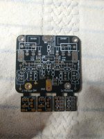
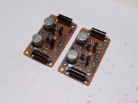
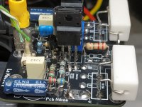
Last night I forgot to put a link to the old version, the difference is that this one is made entirely with SMD tantalum resistors. The regulators as the most important component will also be improved in the style of the regulators from my 'ceci est un cube' amplifier.
Attachments
Hi.
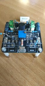
I put the jfets idss 3.09 pair and pair 3.11ma on my board from member Tamra (Thank you )
The trimmer was at 50+50 Ω Rail votages 12.3V +/- batteries.
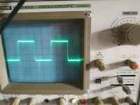
First measure on 1k 1.40V
The target is 1.2V
After calculate the by pass resistor so reduce the current and drop the voltage from 1.40V at 1.20V the resistor is 33k or 27k+5.6k and landed to +1.218V and -1.130V
to make equal the values +/- the trimmer goes to 46/54 Ω
Today i will put the output transistors and the resistors 1Ω if i measure 0.6 A on start up ....fine i will use active pwm fan for cooling.
Everything seems go well.
I put the jfets idss 3.09 pair and pair 3.11ma on my board from member Tamra (Thank you )
The trimmer was at 50+50 Ω Rail votages 12.3V +/- batteries.
First measure on 1k 1.40V
The target is 1.2V
After calculate the by pass resistor so reduce the current and drop the voltage from 1.40V at 1.20V the resistor is 33k or 27k+5.6k and landed to +1.218V and -1.130V
to make equal the values +/- the trimmer goes to 46/54 Ω
Today i will put the output transistors and the resistors 1Ω if i measure 0.6 A on start up ....fine i will use active pwm fan for cooling.
Everything seems go well.
Attachments

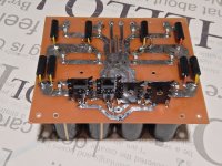
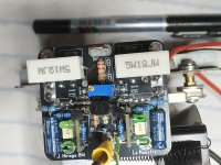
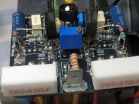
I changed the transistors in the section cascode 1845-992 other hfe.....Now the amp starts on 1 Ω at 530mV and it ends at 800mV bias.
On the resistors 1k i measure at the start 1.20mV which eventually ends up at 1.30mV - 1.35mV , bypass resistor 33k total , maybe i go litle higher So finally to land a little from 1.30 mV on 1k.
About offset 1-5mV the jfets are in face to face thermal coupling Very essential for the good stable operation of this amplifier.
Cascode 1845-992
Drivers 4793-1837
Output 1987-5359
Attachments

Last edited:
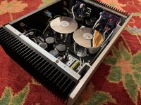
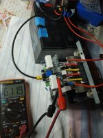
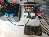
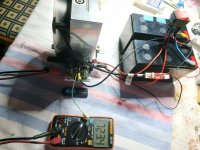
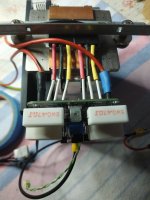
Today I applied voltages of about 23.5 V +/-
And placed feedback resistors of 220 ohms and 22 ohms, for 4 Ω version
Also the bypass resistor reached at 68k. Starting cold on 1k. at 1.20V and with parallel resistors of 1 ohm and 0.47 ohm, .about at 0.319 ohms I reached on the resistors 712mV the bias at 2.23A.
Everything is better rock steady.
The active fan no noise at all ...and the temp on body BJT 50C .
Attachments


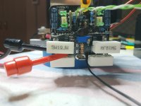
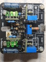
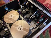
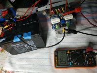
Finally setup for 4Ω version
+/- 22-24V
330pf cap
Bypass resistor 68k
On 1k res cold 1.20V -1.34V
0.47Ω resistor bias 730 -750mv about 1.6A
220 -20Ω gain resistor
Offset +/- 2 mV
Trimmer 100Ω. 53-48 Ω
2sj74Gr -2sk170gr 3.0ma idss
Cascode 1845-992
Drivers 4793-1837
Output 1987-5359
+/- 22-24V
330pf cap
Bypass resistor 68k
On 1k res cold 1.20V -1.34V
0.47Ω resistor bias 730 -750mv about 1.6A
220 -20Ω gain resistor
Offset +/- 2 mV
Trimmer 100Ω. 53-48 Ω
2sj74Gr -2sk170gr 3.0ma idss
Cascode 1845-992
Drivers 4793-1837
Output 1987-5359
Attachments

- Home
- Amplifiers
- Solid State
- Hiraga "Le Monstre"