1. My bad, I assumed that there are some "standard" value inductors in the fans that would fit my circuit... Stupid of me to asume as I didn`t even tell you what trafo I will use, in fact I don`t even know myself as I didn`t look at what I have at home.Various comments:
1.- The inductor from fan was only an example of that you can use an inductor or capacitor to produce a voltage drop. This don't mean that any inductor is just fine for dropping the voltage available to the needs of your heater(s). You will need to do some maths to find the proper one. Not too difficult.
2.- It would be better (ussualy is) to start from a receiver and after the transmitter. Me didn't do it and, like you, started by the end 🙂.
3.- Regens are easy to build and put into service without any further alignment or calibration. In the other hand, you need to "align" you receiver every time you use it, including when changing the frequency of reception.
Regens are in use since more than a century. They are despreciated by novices with lots of knowledge on SDR and expensive digital receivers. But really they continue being the most effective way to have an "all in one" receiver. It may use any valve or JFET. BJT's can do the job too but they are worse than the formers. Certainly properly adjusted (you will need to be trained yourself using your regen, and every regen behaves different from other) they can give you very good audio quality by the fact that only one time the incoming signal is procceded in the receiver.
Regens are like an oscillator. In fact they are used just before they enter in oscillation. Or just into oscillation. Look at this: one triode alone with proper design can receive any kind of signal; maintaining it w/o oscillating and centered in the incomming signal, you can listen perfectly any AM signal with carrier (MW or ham radio AM). Moving it at any of the two selectivity curve sides, slightly off tune, you can listen any FM signal. If you adjust it just to the point it just start to oscillate, you can listen SSB signals (AM with carrier and one sidebands cuted out). Also a CW or Morse Code transmision. What more for so few?
Morever, they do all the processing of the signal in one stage. First, the signal is received and selected by the tuned circuit. The tube close to oscillation behaves as a Q multiplier with increased selectivity than the tuned circuit alone, and amplifies it several times. Thanks to positive feedback, the tube amplifies it much more than its mu factor parameter found in the datasheets. Thus it detects the signal thanks to grid leak. Then the audio signal is newly amplified at audiofrequencies appearing at its plate ready to listen thrugh a couple of high impedance high sentitivity phones. What more you can ask them?
2. Yes, sims logical to me to. Anyway I would like to start with the transmitter as "I`m already in." I have receiver already, by the way this is it`s frequency band:

Bands are marked old Yugoslavian way...
DV -DOLGI VAL - LONG WAVE
SV -SREDNJI VAL - MEDIUM WAVE
KV -KRATKI VAL -SHORT WAVE - AM
UKV - ULTRA KRATKI VAL - ULTRA SHORT WAVE - FM
Mainly all old Yugoslavian radios offered all that bands.
I would like to build regen receiver and join it with the transmitter... but frist thing`s first.
3. I was actually looking at one such receiver project before and I saw a thread on radiomuseum (I don`t know if I`m allowed to post links of other forums here.)
It uses PCF801 tube and it immediately catched my attention, but I wanted to hear from others what could be done with tubes on my list and here I am.
Now that I had read your description about such radio, I`m even more impressed about it and also my understanding is better.
Last edited:
1. Ok. That would be cathode of the triode or the pentode? I would say triode?Don't worry. My native language is Spanish so we are the same situation.
When the oscillator is ready, you can check oscillations by 3 ways:
1.- Hooking an oscilloscope at the oscillator's cathode. You will be able to see a relatively clean sine wave at the crystal's frequency.
2.- If you have a receiver capable of listening short waves. If the crystal is much lower than the receiver's coverage, you can listen it in a harmonic, say, 2; 3 or 4 times crystal fundamental although each higher harmonic is lower in intensity or field strenght.
3.- Having the grid bias leak in the pentode section but leaving plate and screen unpowered, you must be able to read a DC voltage across the grid leak and bypass capacitor. Ideally this voltage would be about 20 to 50VDC negative at the grid side of both.
Any device hooked to the oscillator, loads it and then changues slightly its amplitude and frequency. This is a normal situation. So try to use only one thing wired to the oscillator. Use as short wires compatible with clearness and safety between high voltages (both RF and DC) and ground or AC grounded parts (anode of the triode for example). The oscillator's cathode although it will have few DC volts, it will be live for RF several volts. So, measuring of DC volts at the cathode while the oscillator is active, will cause a digital VOM to become crazy although properly set. This is normal too. This usualy don't cause damage to VOM nor to triode, but expect any unreasonable readings.
2. Short wave on my Savica starts at 5,9mhz, so I will have to listen it in harmonic, at least till I build the receiver.
3. Ok, noted.
4. Ok, also noted.
Now I`m wondering what value resistors / capacitors I should use a a starting point... I understand that it will probably have to be set via trial and error, but for the starting point.
Resistors with 1w power rating should be strong enough for everywhere in the circuit right (Except for the filament drop-down)?
RF chokes... Pair of coils from the second picture from above... I can still try to use them for cathode choke regardless of using PCF802?
That leaves the RF choke below the tank coil and the tank coil. Any specs for making or buying the RF choke? And for the tank coil if I understand correctly I must make it matched it to my xtal? How do I calculate the specs?
If you carefully can dissasemble the two pies from.the antenna in the radio depicted, one of them will be fine for the triode's cathode, and the other for the decoupling choke in the plate circuit. Going deeper, a choke in RF is closely a constant current source device. So there you can have a high impedance to the signal while low DC resistance path to ground.
Triode's grid leak is 100K. Half watt suffices. The plate dropping resistor initially may be 100K too, but it may be decreased in order to get more excitation for the pentode if needed. Here 1W may be necessary.
Previous comments about VOM and the like, refer to PCF802 triode exclusively.
Triode's grid leak is 100K. Half watt suffices. The plate dropping resistor initially may be 100K too, but it may be decreased in order to get more excitation for the pentode if needed. Here 1W may be necessary.
Previous comments about VOM and the like, refer to PCF802 triode exclusively.

ok, thank you... I will see if I can get the coils apart.If you carefully can dissasemble the two pies from.the antenna in the radio depicted, one of them will be fine for the triode's cathode, and the other for the decoupling choke in the plate circuit. Going deeper, a choke in RF is closely a constant current source device. So there you can have a high impedance to the signal while low DC resistance path to ground.
Triode's grid leak is 100K. Half watt suffices. The plate dropping resistor initially may be 100K too, but it may be decreased in order to get more excitation for the pentode if needed. Here 1W may be necessary.
Previous comments about VOM and the like, refer to PCF802 triode exclusively.
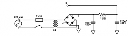
Would this power supply be appropriate for the project? I used this schematic in EL84 amplifier build, B+ is 270VDC
Attachments
I usually like to be concrete with some comments. In some of them I can, in other no. As you are starting a project whose main components aren't well defined (I undertand you are using aged tubes, so we don't know their state, the activity of the crystal, availability of some materials), I can't. Thus I can't be specific on those things.
When l build my first transmiter using a 6DQ6 from horizontal sweep in TV's, exausted tubes for such a service, were relatively fine for my TX. Class C amplifiers and oscilators need a very short pulse of current plate as intense as the tube can. So, with a new pentode one can obtain 30/35 RF Watts while an aged can do it at 20 or 25. The cloud of electrons generated by the cathode between it and the grid can be sufficient still in an aged tube to perform quite well.
When l build my first transmiter using a 6DQ6 from horizontal sweep in TV's, exausted tubes for such a service, were relatively fine for my TX. Class C amplifiers and oscilators need a very short pulse of current plate as intense as the tube can. So, with a new pentode one can obtain 30/35 RF Watts while an aged can do it at 20 or 25. The cloud of electrons generated by the cathode between it and the grid can be sufficient still in an aged tube to perform quite well.
Yeah. I suggest to add a ceramic .01uF on each 'lytic as they aren't good for RF decoupling. Also add .001 across each diode for the same reason. All may be those ceramic caps @1KV blue colored available in many shops and SMPS to reuse.ok, thank you... I will see if I can get the coils apart.
Would this power supply be appropriate for the project? I used this schematic in EL84 amplifier build, B+ is 270VDC
Ok will do as so.Yeah. I suggest to add a ceramic .01uF on each 'lytic as they aren't good for RF decoupling. Also add .001 across each diode for the same reason. All may be those ceramic caps @1KV blue colored available in many shops and SMPS to reuse.
Ok, understood. I think that I have enough info for now to start with the build. I had also looked at some other builds and got ideas about values and functions of some components. I will start writting known values to the schematic and see where I am. If I understood correctly those are the coils I will use, right?I usually like to be concrete with some comments. In some of them I can, in other no. As you are starting a project whose main components aren't well defined (I undertand you are using aged tubes, so we don't know their state, the activity of the crystal, availability of some materials), I can't. Thus I can't be specific on those things.
When l build my first transmiter using a 6DQ6 from horizontal sweep in TV's, exausted tubes for such a service, were relatively fine for my TX. Class C amplifiers and oscilators need a very short pulse of current plate as intense as the tube can. So, with a new pentode one can obtain 30/35 RF Watts while an aged can do it at 20 or 25. The cloud of electrons generated by the cathode between it and the grid can be sufficient still in an aged tube to perform quite well.

Only one thing I'm having hard time with... It's the tank coil... I'm searching and searching, but can't seem to find much info on it.
Should it be something like that?

Or more like that?

Distance between the two coils must be adjustable?
I had also seen small coil over bigger one and ferrite core inside that moves up and down to change inductance. Would that fit?
Just to confirm on the smaller coil, upper end would go to antenna and lower end to ground or not connected?

Last edited:
Tank coil may have any form. For tube circuits generally are air cored but no allways. From a single layer of wire to copper tubing inside them running water for cooling, at very high power. Remember the old times when short wave emmiters had 500 to 1000 KW. Our one will be more like the one wired over a white plastic tube. But have patience. First take the oscillator running and let time yourself to enjoy building the project and familiarize with circuit topology. Tubes and solid state are different in several aspects but similar in others.
In the coil of the first pic, try to leave the dual pie coils over the bobbin alone. If possible, get rid of the other coils.
In the coil of the first pic, try to leave the dual pie coils over the bobbin alone. If possible, get rid of the other coils.
Ok, thank you for explanation. I tought that I need it to get oscillator running... If I take a look at a circuit and taught about how it works, it's clear that I don't need it...Tank coil may have any form. For tube circuits generally are air cored but no allways. From a single layer of wire to copper tubing inside them running water for cooling, at very high power. Remember the old times when short wave emmiters had 500 to 1000 KW. Our one will be more like the one wired over a white plastic tube. But have patience. First take the oscillator running and let time yourself to enjoy building the project and familiarize with circuit topology. Tubes and solid state are different in several aspects but similar in others.
In the coil of the first pic, try to leave the dual pie coils over the bobbin alone. If possible, get rid of the other coils.
Well with that out of the way I can start building the oscillator. I will have to wait till the monday so I can get the resistors & caps, but will look if maybee I can source everything at home.
Will get rid of other coils, no problem.
There is an application for audio, and it was published in Linear Audio Volume 6. Title: Multiplied transconductance Amplifiers. Author: Frank Blöhbaum.ECH84 has and hexode and a triode sharing common cathode, designed for mix and converters in radio. A bit difficult to find application at audio.
I liked the article quite a bit because it combined tubes with semiconductors in a way to make the best of both, to achieve very low distortion while maintaining the famous sound signature (mainly 2nd harmonic) of a single ended triode amp. Probably the best part has yet to be published: using a cascode with medium power MJT "below" and power triode "above", such a stage attains close to 50% efficiency while maintaining that characteristic triode sound signature.
Most tubes can perform better than datasheets mention. Very long ago I made a low power oscillator with a 6D6 (Variable u pentode) on batteries and the 6V for the heater also was used for anode and screen supply. Using a loudspeaker for microphone, it was my first AM transmitter. Also, tubes for 9V can be run on 6V as long as the tube is working far enough below the maximum specifications. There even exist passive mixer circuits with tubes (they don't need power supply apart from heater).Ok, thank you for explanation. I tought that I need it to get oscillator running... If I take a look at a circuit and taught about how it works, it's clear that I don't need it...
Well with that out of the way I can start building the oscillator. I will have to wait till the monday so I can get the resistors & caps, but will look if maybee I can source everything at home.
Will get rid of other coils, no problem.
True, rectifying the 6.3V heater supply did the job. Before semiconductors took over, car radios were fitted with tubes designed for low voltage, like the ECH83. Although designed as (noisy!) frequency changer (mixer) it could be the perfect tube for a "safe" (no dangerous HV) yet sensitive regen RX.Curiously regens work best with lower voltages and low mu triodes. 9V were common practice.
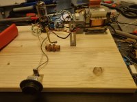
I had made the oscillator. But I need to get probes for oscilloscope because I can only apply 50vpk max with :1 probes.
B+ is 300vdc and falls to 295vdc when tube warms up... Is this good or to high?
What is the maximum frequency of crystal that I could use?
My radio goes from 5.9mhz to 7.45mhz... So I cant listen either at 4.433mhz or the harmonics... I can hear that radio gets a bit quieter at around 6.6mhz when I turn on the oscillator.
Attachments
You can make a natural attenuator for RF. Only take about 10~15cm of copper wire plastic or enamel isolated. Peel both ends. One end to the tip of the oscilloscope. The other end to the ground clip (usually an alligator clip). Give it the form of a round loop.
You surely will think its a simple shortcircuit and this is thus, useless.
Halt: This is true for DC and low frequencies, but NO at radiofrequencies!!!. You had built a secondary single turn of a RF transformer whose primary may be any wire conducting RF: the choke is the best primary. But any conductor in the circuit conducting RF currents radiate it. Why not to try it?
300V for a crystal oscillator is too high. 150DCV is more proper. This may be adjusted with the decoupled anode resistor. Crystal may be any whose frequency may be received in your SW set.
Last edited:
I did make the attenuator, but my o-scope is no good. It's a cheap portable one and it only reads up to 200khz...You can make a natural attenuator for RF. Only take about 10~15cm of copper wire plastic or enamel isolated. Peel both ends. One end to the tip of the oscilloscope. The other end to the ground clip (usually an alligator clip). Give it the form of a round loop.
You surely will think its a simple shortcircuit and this is thus, useless.
Halt: This is true for DC and low frequencies, but NO at radiofrequencies!!!. You had built a secondary single turn of a RF transformer whose primary may be any wire conducting RF: the choke is the best primary. But any conductor in the circuit conducting RF currents radiate it. Why not to try it?
300V for a crystal oscillator is too high. 150DCV is more proper. This may be adjusted with the decoupled anode resistor. Crystal may be any whose frequency may be received in your SW set.
However if I set it up to 5mv and 5ms I can see the 50hz from mains and when I turn the oscillator on it flattens that 50hz pickup, so it must be doing something....
I did managed to get 6mhz crystal so I can try it with the receiver, there was silence below about 6.5mhz yesterday when I was listening thru the band, but maybee I will be able to hear some difference...
I will figure out the resistor value to get 150vdc....
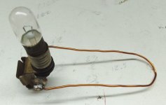
Nice. What would be the bulb voltage / power rating?For the task of testing the output tube, you will need to build this extremelly complicated device. This is sometimes called "Hertz loop".
- Home
- Amplifiers
- Tubes / Valves
- Help me put these tubes into good use... I need a project