This is an easy to build QRP (low power using ham radio dixit) you can build.
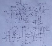
Note the use of two tubes. Triode PCL85 oscillates crystal controlled. Frequency depend exclusively on crystal. Pentode amplifies the oscillation runing both class C.
PCL86 triode amplfies the signal coming from any audio source: a dynamic microphone, a small speaker used as mike, and the pentode augments audio power. As the pentode ECL85 takes energy from PCL86 pentode, if audio is at the plate, the amplitude of the oscillations will increase or decrease acording audio signal, thus a simple AM transmiter is built.
Plate tank labeled is a coil you will need to build yourself and will depend on frequency of crystal. So when the later is defined, the former too. The variable capacitor at plate of PCL85 may be one section of an AM radio of the air dielectric type (not polivaricon).
The screen dropping resistor must be adjusted in service. For security of the tube, a 100K resistor @1W may success, but posibly when the TX is finished, and if no red plating at pentode, this resistor can be reduced to allow a higher power. The bipolar capacitor in parallel may be any good 10uF@400VDC and enables screen grid be feeded with audio signal too. All .001 and .01uF must be ceramic or mica, not less than 500VDC.
Attachments

Ok, I had just arrived from work. I will start with hunt for parts in about an hour. But i don't have the PCL85, can I replace it with something I have on the list? I will order it otherwise....This is an easy to build QRP (low power using ham radio dixit) you can build.
Note the use of two tubes. Triode PCL85 oscillates crystal controlled. Frequency depend exclusively on crystal. Pentode amplifies the oscillation runing both class C.
PCL86 triode amplfies the signal coming from any audio source: a dynamic microphone, a small speaker used as mike, and the pentode augments audio power. As the pentode ECL85 takes energy from PCL86 pentode, if audio is at the plate, the amplitude of the oscillations will increase or decrease acording audio signal, thus a simple AM transmiter is built.
Plate tank labeled is a coil you will need to build yourself and will depend on frequency of crystal. So when the later is defined, the former too. The variable capacitor at plate of PCL85 may be one section of an AM radio of the air dielectric type (not polivaricon).
The screen dropping resistor must be adjusted in service. For security of the tube, a 100K resistor @1W may success, but posibly when the TX is finished, and if no red plating at pentode, this resistor can be reduced to allow a higher power. The bipolar capacitor in parallel may be any good 10uF@400VDC and enables screen grid be feeded with audio signal too. All .001 and .01uF must be ceramic or mica, not less than 500VDC.
You had also mentioned ECL85, did you mean PCL?
Member
Joined 2009
Paid Member
I dunno, seems a big step at first to be building a multi tube transmitter - and no equipment to check the output of the transmitter for spurious interference that it might be generating etc. I'm no radio buff, but if it has to be a transmitter why not a simple keyed CW transmitter which is simpler? (Google One Tube CW Transmitter) or why not an h.f. receiver instead? just sayin
There are MANY interesting websites to research this, e.g. https://onetuberadio.com/2017/03/25/1967-one-tube-cw-transmitter/
There are MANY interesting websites to research this, e.g. https://onetuberadio.com/2017/03/25/1967-one-tube-cw-transmitter/
PCL85 is roughly to PCL805 your mentioned at first post. My apologies for those typos.
Prior to put hand to work, l suggest you to take some readings about tubes, their habbits and mainly how do they are operated as Class C.
Forgot some words about the milliammeter. It will be needed to properly adjust tank circuit to resonance. Any moving coil instrument with a full range of 50mA will suffice. But nowadays those instrumemts are difficult to find. You can also use a vumeter of the used in cassette players and make a proper shunt for it.
Attachments
Because mainly I hate CW and rarely the guy knows Morse code. In any way, an impropely adjusted CW TX is worsen than an AM one because the ellimination of blurrs of the signal is a hard task. And to receive CW signals he need a communications receiver with beat oscillator or SSB. AM can be checked in any common receiver.I dunno, seems a big step at first to be building a multi tube transmitter - and no equipment to check the output of the transmitter for spurious interference that it might be generating etc. I'm no radio buff, but if it has to be a transmitter why not a simple keyed CW transmitter which is simpler? (Google One Tube CW Transmitter) or why not an h.f. receiver instead? just sayin
There are MANY interesting websites to research this, e.g. https://onetuberadio.com/2017/03/25/1967-one-tube-cw-transmitter/
Member
Joined 2009
Paid Member
I don't feel hold back because of the size of the project. It wont be the first time, it's just I work with ic's and other newer components...I dunno, seems a big step at first to be building a multi tube transmitter - and no equipment to check the output of the transmitter for spurious interference that it might be generating etc. I'm no radio buff, but if it has to be a transmitter why not a simple keyed CW transmitter which is simpler? (Google One Tube CW Transmitter) or why not an h.f. receiver instead? just sayin
There are MANY interesting websites to research this, e.g. https://onetuberadio.com/2017/03/25/1967-one-tube-cw-transmitter/
I built EL84 amplifier few years back... so it's not exactly first tube project.
Will do.
Ok, will do the reading.PCL85 is roughly to PCL805 your mentioned at first post. My apologies for those typos.
Prior to put hand to work, l suggest you to take some readings about tubes, their habbits and mainly how do they are operated as Class C.
Forgot some words about the milliammeter. It will be needed to properly adjust tank circuit to resonance. Any moving coil instrument with a full range of 50mA will suffice. But nowadays those instrumemts are difficult to find. You can also use a vumeter of the used in cassette players and make a proper shunt for it.
I don't have milliammeter, but I do have spare vumeter.
I hope something will be usefull from there, I must translate writings on some crystals, but I think the lowest I have is 4.433mhz.
There are the coils from the savica radio:

Left part, two coils wired in series, one small is also located green coil under the right coil:

Right part, two coils:

4 small coils with pigtails:

Trimmer:

Whole thing:

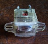
Coils from hifi system, where antenna connects:

Chokes from TV board on high voltage side:

Oh, I opened it and saw all the chokes so I figured it was for me.Ok. Read it if you want, but this link was directed mainly for @Bigun.
I do have some crystals labeled like "D400J3I", D169D0I" and so on, but google wont find anything... so 4.433mhz is the lowest. Will it be ok?
The gang (you called trimmer) above depicted is pretty fine for final tank. 4.433 is fine too. The coils from PC monitor or TV's don't work fine at HF. Those ferrite coils are good only up to 150 or 200KHz. And has too high internal parasitic capacitance.
The pair of coils at second pic may be fine for cathode choke at oscillator stage.
The proper sequence of facts ideally are:
1. To make the oscillator to work fine.
2. To make the RF amplifier to work fine too. To do this job, you will need the mA and a small lamp such those used in radio dials. No neon nor led: filamentary lamp.
3. To assemble audio amplifier and couple it to the RF stage.
4. Check modulation in a short wave receiver.
This is the best part. You will listen it at 4.433 and harmonics because of proximity of tx and rx will put the last close to saturation.
Ok, yesterday I watched alot of radio / tube theory before I went a sleep. Didn't manage to learn about class C yet... but today I examined schematic that you gave me together with it's describtion and I understand it.The gang (you called trimmer) above depicted is pretty fine for final tank. 4.433 is fine too. The coils from PC monitor or TV's don't work fine at HF. Those ferrite coils are good only up to 150 or 200KHz. And has too high internal parasitic capacitance.
The pair of coils at second pic may be fine for cathode choke at oscillator stage.
The proper sequence of facts ideally are:
1. To make the oscillator to work fine.
2. To make the RF amplifier to work fine too. To do this job, you will need the mA and a small lamp such those used in radio dials. No neon nor led: filamentary lamp.
3. To assemble audio amplifier and couple it to the RF stage.
4. Check modulation in a short wave receiver.
This is the best part. You will listen it at 4.433 and harmonics because of proximity of tx and rx will put the last close to saturation.
I will stop at electronics shop before I go to work to get some sockets, resistors, capacitors, ....
Maybee they have the chokes... what would be the values I need?
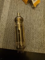
Looks like I will need to order PCL805... this is the only tube that have signs of use and text came off... it was stored in PCL805 box and somebody written PCL805 on there one more time by hand.... but it has metal cap... this can't be the right one. Thankfully PCL86 looks brand new.
Attachments
- Home
- Amplifiers
- Tubes / Valves
- Help me put these tubes into good use... I need a project