I "designed" this circuit according to those tubes listed in post #1. But if you have another, the design can be midified for them.TUBE LIST:
PL504
PCF801
PCF802
ECH84
PCL805 <<<
PCL86 <<<
PCC88
There is 1 piece of each, sadly no pairs...

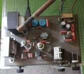
I had examined the schematic for resistors and capacitors I need to buy and I wonder what values should I get for R1, C1, C2, resistor going from the PCL86's pentode cathode towards the ground (parallel with 100uF capacitor) and from PCL86's triode grid towards the ground (parallel with 100pF capacitor on the input). I understand that this will need to be set, but what would be the starting point.The gang (you called trimmer) above depicted is pretty fine for final tank. 4.433 is fine too. The coils from PC monitor or TV's don't work fine at HF. Those ferrite coils are good only up to 150 or 200KHz. And has too high internal parasitic capacitance.
The pair of coils at second pic may be fine for cathode choke at oscillator stage.
The proper sequence of facts ideally are:
1. To make the oscillator to work fine.
2. To make the RF amplifier to work fine too. To do this job, you will need the mA and a small lamp such those used in radio dials. No neon nor led: filamentary lamp.
3. To assemble audio amplifier and couple it to the RF stage.
4. Check modulation in a short wave receiver.
This is the best part. You will listen it at 4.433 and harmonics because of proximity of tx and rx will put the last close to saturation.
EDIT: will wait so we solve the tube situation first.
Yes, I tought that I have it, but it looks like it was just the box.... what is that tube inside I don't knowI "designed" this circuit according to those tubes listed in post #1. But if you have another, the design can be midified for them.
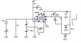
Those 100pf caps spared at the audio section are to get rid of RF induction at them which usualy causes audio distortion and or oscillation of audio stage.
Don't worry. Almost all audio tubes work pretty well at frequencies up to 30MHz so we can readily update the circuit to use what you have. No need for buying nothing. Ham radio usually does the rigs with what he has in the junk.
There was an era (I did't live it myself) in where the variable capacitor (gang) wasn't available. So old hams made his own using half part of thinker from metal cans from caned food.
Last edited:
Some tubes don't add up... I'm sorry about that... I received alot of stuff in boxes, nicely sorted, with labels, some tubes dont have writtings on them, but they were in the boxes, models written on boxes by hand... so I assumed that they are what it says on the box and filament voltages matched to specs....Yes, I tought that I have it, but it looks like it was just the box.... what is that tube inside I don't know
I will go thru one more time now and report back only tubes that have writtings visible on the tube itself... Sorry once again.
Its OK. Don't worry. Enjoy. Don't, never forget this is a hobbie.
I can't be mad on myself... it's just that you spent your time to design a schematic for me for wrong tube, due to my error and I feel bad for it.Its OK. Don't worry. Enjoy. Don't, never forget this is a hobbie.
That's good. I must go to work and I will stop at the shop anyway for tube sockets, transformer and I will see what RF chokes they offer.Thus maintain the '86 for audio and use for RF stage the '802. Same circuit but pin # of tubes will be different. Some minor changes also in the passive components.
Should I get 1:1 transformer or something else? We have 220vac mains.That's good. I must go to work and I will stop at the shop anyway for tube sockets, transformer and I will see what RF chokes they offer.
It will depend on how will you energyze tube heaters. If a transformer for each one providing them have different heater ratings, one trafo for both or a dropping element from a higher voltage. Usualy string heaters used a resistor to waste the difference from line voltage and series summation of heater voltages into wasted heat. More recently a capacitor carefully designed was used with less heat inside cabinet. Also an AC choke may be used like those used in AC fans with 3 or more speeds, they got an inductor in series with the motor tapped properly for each speed. At maximum, choke was out of circuit.
I suggest also use PCC88 for a funny regenerative receiver. This was one of the common type prior to development of superheterodyne kind of receiver. It's a tube too "good" for it. "Regens" perform best with worse primitive tubes, curiously.
This is a good example. Changing 6SN7 for your PCC88 is simple and easy.
Enjoy the simplicity, economy of a regen, at the price of s higher complexity in use. This is my regen for commercial AM MW. An ECF801, ECL85 & 6X4. No more needed.
This is a good example. Changing 6SN7 for your PCC88 is simple and easy.
Enjoy the simplicity, economy of a regen, at the price of s higher complexity in use. This is my regen for commercial AM MW. An ECF801, ECL85 & 6X4. No more needed.
Attachments
Last edited:
Yes, I forgot to mention that I'm buying a transformer only for main supply.It will depend on how will you energyze tube heaters. If a transformer for each one providing them have different heater ratings, one trafo for both or a dropping element from a higher voltage. Usualy string heaters used a resistor to waste the difference from line voltage and series summation of heater voltages into wasted heat. More recently a capacitor carefully designed was used with less heat inside cabinet. Also an AC choke may be used like those used in AC fans with 3 or more speeds, they got an inductor in series with the motor tapped properly for each speed. At maximum, choke was out of circuit.
Getting a transformer with multiple outputs except for center tap isn't possible where I live..
I will see later what I will do with heaters. Either one trafo per bulb or a drop-down... I do have one faulty 3 speed ac fan, so I might use inductor from there....
I grabbed 230v 1:1 50VA transofrmer, will 50VA be enough?
Sadly they didn't had sockets for tubes... after a lot of searching, seller turned to me and said "This is antique, what are you even gonna do with it"... Welcome to Slovenia 😆
I think that I should have 2 sockets somewhere, but I also took few connectors that will fit the tube pins good so I can start working, but I will order some online, if I don't find sockets at home...
Sadly no RF chokes, except for toroid type ones for car radio psu filtering and such... will have to order online or make those too...
Nice project, I also took the time yesterday and had a look at two other projects of yours that you linked yesterday... wow, its nice.I suggest also use PCC88 for a funny regenerative receiver. This was one of the common type prior to development of superheterodyne kind of receiver. It's a tube too "good" for it. "Regens" perform best with worse primitive tubes, curiously.
This is a good example. Changing 6SN7 for your PCC88 is simple and easy.
Enjoy the simplicity, economy of a regen, at the price of s higher complexity in use. This is my regen for commercial AM MW. An ECF801, ECL85 & 6X4. No more needed.
I will look into receiver, but I should really finish the transmitter first.
Looks like a damper diode to me, something like a PY800.Looks like I will need to order PCL805... this is the only tube that have signs of use and text came off... it was stored in PCL805 box and somebody written PCL805 on there one more time by hand.... but it has metal cap... this can't be the right one. Thankfully PCL86 looks brand new.
Various comments:
1.- The inductor from fan was only an example of that you can use an inductor or capacitor to produce a voltage drop. This don't mean that any inductor is just fine for dropping the voltage available to the needs of your heater(s). You will need to do some maths to find the proper one. Not too difficult.
2.- It would be better (ussualy is) to start from a receiver and after the transmitter. Me didn't do it and, like you, started by the end 🙂.
3.- Regens are easy to build and put into service without any further alignment or calibration. In the other hand, you need to "align" you receiver every time you use it, including when changing the frequency of reception.
Regens are in use since more than a century. They are despreciated by novices with lots of knowledge on SDR and expensive digital receivers. But really they continue being the most effective way to have an "all in one" receiver. It may use any valve or JFET. BJT's can do the job too but they are worse than the formers. Certainly properly adjusted (you will need to be trained yourself using your regen, and every regen behaves different from other) they can give you very good audio quality by the fact that only one time the incoming signal is procceded in the receiver.
Regens are like an oscillator. In fact they are used just before they enter in oscillation. Or just into oscillation. Look at this: one triode alone with proper design can receive any kind of signal; maintaining it w/o oscillating and centered in the incomming signal, you can listen perfectly any AM signal with carrier (MW or ham radio AM). Moving it at any of the two selectivity curve sides, slightly off tune, you can listen any FM signal. If you adjust it just to the point it just start to oscillate, you can listen SSB signals (AM with carrier and one sidebands cuted out). Also a CW or Morse Code transmision. What more for so few?
Morever, they do all the processing of the signal in one stage. First, the signal is received and selected by the tuned circuit. The tube close to oscillation behaves as a Q multiplier with increased selectivity than the tuned circuit alone, and amplifies it several times. Thanks to positive feedback, the tube amplifies it much more than its mu factor parameter found in the datasheets. Thus it detects the signal thanks to grid leak. Then the audio signal is newly amplified at audiofrequencies appearing at its plate ready to listen thrugh a couple of high impedance high sentitivity phones. What more you can ask them?
I will do the oscillator first as you suggested.Various comments:
1.- The inductor from fan was only an example of that you can use an inductor or capacitor to produce a voltage drop. This don't mean that any inductor is just fine for dropping the voltage available to the needs of your heater(s). You will need to do some maths to find the proper one. Not too difficult.
2.- It would be better (ussualy is) to start from a receiver and after the transmitter. Me didn't do it and, like you, started by the end 🙂.
3.- Regens are easy to build and put into service without any further alignment or calibration. In the other hand, you need to "align" you receiver every time you use it, including when changing the frequency of reception.
Regens are in use since more than a century. They are despreciated by novices with lots of knowledge on SDR and expensive digital receivers. But really they continue being the most effective way to have an "all in one" receiver. It may use any valve or JFET. BJT's can do the job too but they are worse than the formers. Certainly properly adjusted (you will need to be trained yourself using your regen, and every regen behaves different from other) they can give you very good audio quality by the fact that only one time the incoming signal is procceded in the receiver.
Regens are like an oscillator. In fact they are used just before they enter in oscillation. Or just into oscillation. Look at this: one triode alone with proper design can receive any kind of signal; maintaining it w/o oscillating and centered in the incomming signal, you can listen perfectly any AM signal with carrier (MW or ham radio AM). Moving it at any of the two selectivity curve sides, slightly off tune, you can listen any FM signal. If you adjust it just to the point it just start to oscillate, you can listen SSB signals (AM with carrier and one sidebands cuted out). Also a CW or Morse Code transmision. What more for so few?
Morever, they do all the processing of the signal in one stage. First, the signal is received and selected by the tuned circuit. The tube close to oscillation behaves as a Q multiplier with increased selectivity than the tuned circuit alone, and amplifies it several times. Thanks to positive feedback, the tube amplifies it much more than its mu factor parameter found in the datasheets. Thus it detects the signal thanks to grid leak. Then the audio signal is newly amplified at audiofrequencies appearing at its plate ready to listen thrugh a couple of high impedance high sentitivity phones. What more you can ask them?
I had some free time (I work on demand) and managed to draw schematic for PCF802 on work computer.
I figured it will be simpler to label all the components with numbers and I can update the values on it as needed.
I don't have time right now to read and reply as I need a bit longer because of english isn't my native language, but will do it ASAP when I get home.
Attachments
Don't worry. My native language is Spanish so we are the same situation.
When the oscillator is ready, you can check oscillations by 3 ways:
1.- Hooking an oscilloscope at the oscillator's cathode. You will be able to see a relatively clean sine wave at the crystal's frequency.
2.- If you have a receiver capable of listening short waves. If the crystal is much lower than the receiver's coverage, you can listen it in a harmonic, say, 2; 3 or 4 times crystal fundamental although each higher harmonic is lower in intensity or field strenght.
3.- Having the grid bias leak in the pentode section but leaving plate and screen unpowered, you must be able to read a DC voltage across the grid leak and bypass capacitor. Ideally this voltage would be about 20 to 50VDC negative at the grid side of both.
Any device hooked to the oscillator, loads it and then changues slightly its amplitude and frequency. This is a normal situation. So try to use only one thing wired to the oscillator. Use as short wires compatible with clearness and safety between high voltages (both RF and DC) and ground or AC grounded parts (anode of the triode for example). The oscillator's cathode although it will have few DC volts, it will be live for RF several volts. So, measuring of DC volts at the cathode while the oscillator is active, will cause a digital VOM to become crazy although properly set. This is normal too. This usualy don't cause damage to VOM nor to triode, but expect any unreasonable readings.
Note: old guys like me call VOM to an Volt-Ohm-Milliameter measuring device, be it analog or digital. Nowadays, digital one includes diode, frequency, hfe, etc measurings and had called them multimeter.
- Home
- Amplifiers
- Tubes / Valves
- Help me put these tubes into good use... I need a project