Compensation: then your design is lucky.
I tried to simulate my amp of course but found even at early experiments
that it's not working in my case just as the guys said a few posts above.
Maybe these drivers are too underhand ones, maybe I swap them tomorrow for the ones Sajti recommended...
Does anyone have any idea how it can happen that the amp is stable without input LP cap and oscillating with it?!
And a reason for what I observed with the OPS bias settings with the base stoppers used @ the drivers?
Compensation: then your design is lucky.
I tried to simulate my amp of course but found even at early experiments
that it's not working in my case just as the guys said a few posts above.
Maybe these drivers are too underhand ones, maybe I swap them tomorrow for the ones Sajti recommended...
Does anyone have any idea how it can happen that the amp is stable without input LP cap and oscillating with it?!
And a reason for what I observed with the OPS bias settings with the base stoppers used @ the drivers?
Compensation isn't luck. It's design. You need to master using LTSpice to analyse your control loops. Tian probe etc.
The drivers are fine just need to be treated properly.
The LP cap has a significant effect on loop stability margins. When you get into loop analysis you see how much it changes the overall stability of the amplifier.
Don't give up on this. The learning curve is steep but satisfying.
Paul
Thanks Paul!
And can somebody give me the algorithm how I can solve this systematically?
Now I feel I am just trying blindly to put different value capacitors/resistors here and there...
Are there some fix points in this process? For example:
Or it's working 100%-ly for everyone else..?! 🙄
And can somebody give me the algorithm how I can solve this systematically?
Now I feel I am just trying blindly to put different value capacitors/resistors here and there...
Are there some fix points in this process? For example:
- Should I take out the input LP filter cap through the stabilization process
and just put it in at the and when everything else is stable without it? - How can I separate whether these oscillations are originated from the IPS or OPS or both..?!
- How should I know where to put compensating caps in my amp? There are a lot of possibilities/combinations.
- How should I test whether its OK? 100kHz 50Vpp square wave without any ringing?
Or it's working 100%-ly for everyone else..?! 🙄
The first step is to put this schematic into LTSpice. If you've done this already then please let me know which post I can find it. Use the spice models provided by Bob Cordell. I have models for the A1930/C5171 driver transistors.
Get the schematic to the point where you can run a transient analysis. Then I will add in some Tian probe loop analysis tools provided by David Zan. These are very useful for simultaneously analysing two loops. In your case they are the main feedback loop and the loop generated by the 3p9 caps. The stability of one loop affects the other. You can be in a situation where you improve the stability of one loop and take away stability from the other.
I spent many hours working out how to compensate an amp. Understanding how to design compensation is essential to amplifier design. Personally, I don't see how you can design a sucessfull amp without a basic understanding of loop theory. My latest amp ran straight off from the simulated design. So LTSpice is very usefull.
Paul
As it seems me neither... 🙂I don't see how you can design a sucessfull amp without a basic understanding of loop theory.
Spice: here it comes! But I only used it with ideal BJTs. I dont know how to use the Cordell modells.
Are there correct modells for all my type? I dont know the "Tian" probe method.
Input & PS C multiplier: BC546B/556B
CCS: MPSA18
VAS & Pre & Vbe: 2SA1360/2SC3423
Driver: 2SA1930/2SC5171
Power: NJW0281/NJW0302
If you tell me how I'll do it.
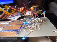
And here is a picture of my poor little "overcompensated" IPS as well... 🙂
Attachments
And it took me a several weeks to achieve a still oscilalting amp... 😛I spent many hours working out how to compensate an amp.
BTW: we can apply a "tabula rasa", I am not sticked to the actual compensation at all.
It is just a result of some rule of thumb + real world experiments but nothing (science based) else...
Are there now some fashionable ones? TPC?
As it seems me neither... 🙂
Spice: here it comes! But I only used it with ideal BJTs. I dont know how to use the Cordell modells.
Are there correct modells for all my type? I dont know the "Tian" probe method.
Input & PS C multiplier: BC546B/556B
CCS: MPSA18
VAS & Pre & Vbe: 2SA1360/2SC3423
Driver: 2SA1930/2SC5171
Power: NJW0281/NJW0302
If you tell me how I'll do it.
And here is a picture of my poor little "overcompensated" IPS as well... 🙂
Have to start somewhere 🙂
Use google to find spice models if they exist.
One way is this. You navigate to standard.bjt and copy the spice models into that text file. You can use note pad. You may need to change permissions in windows to allow the file to be saved. This method is ok as long as you provide a text file containing all non standard models used with the .asc file when posting. This is my favoured method.
The Bob Cordell models can be found at his site.
The new transistor types are then available within LTSpice.
There are other ways of doing this. Like adding a Spice Directive to the schematic with the spice models within it.
Others may be of more help with alternative / better methods.
Here are two models to get you started....
.MODEL 2SA1930_D PNP(
+IS=1.573e-12 NF=1.04 RB=20 RBM=0.1 IRB=10 VAF=83
+BF=250 NE=2.154 ISE=1e-15 IKF=7 NK=0.85
+BR=4 IKR=1.05 VAR=8.3
+TF=455e-12 VTF=2.2 FC=0.5 XTF=5500 ITF=40
+CJE=640e-12 MJE=0.52939885 VJE=0.814106
+CJC=112.474e-12 MJC=0.535605 VJC=0.805555
+TNOM=25 Vceo=180 Icrating=2 mfg=Toshiba)
.MODEL 2SC5171_D NPN(
+IS=549.422e-15 NF=1.017914574 RB=9.805 RBM=0.1 IRB=10 VAF=250
+BF=198 NE=2.0 ISE=1e-16 IKF=1.5
+TF=700e-12 VTF=5 FC=0.5 XTF=500 ITF=20
+CJE=750e-12 MJE=0.332617 VJE=.378977
+CJC=56.636e-12 MJC=0.466097542 VJC=0.577374486
+TNOM=25 Vceo=180 Icrating=2 mfg=Toshiba)
BC546/556 can be substituted with BC550/560.
NJW0281/NJW0302 Cordell models available. (EDIT: Sorry, not this exact type but similar)
2SA1360/2SC3423, MPSA18 not sure about models...
An LTSpice simulation with ideal transistors is no good for designing with. So this is an essential step. 🙂
Hope this is of some help.
Paul
Last edited:
And it took me a several weeks to achieve a still oscilalting amp... 😛
BTW: we can apply a "tabula rasa", I am not sticked to the actual compensation at all.
It is just a result of some rule of thumb + real world experiments but nothing (science based) else...
Are there now some fashionable ones? TPC?
You've built something which is good. 🙂
Something to work with. For now, forget all 2nd order compensation like TPC/TMC and stick with first order like MIC.
I added the types I could...
Hehe, even I forgot my experimental design: I used BCs even @ VAS at the "left" side.
As long they can handle the dissipation I would like to try them out (reason: high speed + beta).
Spice: I have a lib with a lot of standard types (BC, MPSA, ...), I attached it.
The others I dont know how to add... I tried to include the txts and edit the
components (change the NPN/PNP texts to the actual modell ID...) but its not working.
I'll check it tomorrow... (I guess this model-adding feature is not so user friendly in LT...)
Attachments
Hopefully I managed to export all my transistor models now to a separete txt now as attached.
All my Qs have now an "x" suffix. I used MJL4281C/MJL4302C from the Cordell models instead
of NJW0281/NJW0302 and the standard library for the other types. It's ok?
BTW: If there isn't a specific model for my OS Qs it's still gonna work..?
And whats next? (DC OP is looking good and OPS bias + DC servo adjusted...)
Attachments
Last edited:
Ok but after that how should I start the compensation process..?
A started to play with the caps is LT as well but without a systematic process it's still like a lottery
just like on the real amp. Plus if I managed here I guess it wont be 100% the same in reality.
Isn't there an "algorithm" kind of thing to this process?
Hundreds of amps are built in this forum how do you do this part guys..? 🙂
Base-stoppers
Lower or loose the basestoppers on the predrivers, stability is most probably affected.
Lower or loose the basestoppers on the predrivers, stability is most probably affected.
Thanks Piersma, I checked it in LT but thats also not helping.
I tried to check the open loop bode as attached based on this layout:
Solutions - LTspice IV: Stability of Op Amp Circuits
Can someone please check whether it looks OK?
Any further advices are welcome, I'd be very happy to make this amp work properly... 🙂
I tried to check the open loop bode as attached based on this layout:
Solutions - LTspice IV: Stability of Op Amp Circuits
Can someone please check whether it looks OK?
Any further advices are welcome, I'd be very happy to make this amp work properly... 🙂
Attachments
Hi Cortez,
Apologies, noticed there is still a problem (a peaking in the closed loop response) with the version of the amp I posted earlier. It is the lead cap across your feedback resistor. Without this cap using the non Tian loop gain analysis, the main loop looks to have approx PM=84 degrees, GM = 28dB @ ULGF = 621Khz.
Hopefully this version is better. Let me know what you think. I think the peaking has gone? Late here and getting tired. 🙂
Paul
Attachments
Last edited:
Paul, thank you very much, I really appreciate your time!
I'll check it tomorrow, now it's late here too... 🙂
I am curious after the Spice phase how it will relate with the real one... 🙂
I'll check it tomorrow, now it's late here too... 🙂
I am curious after the Spice phase how it will relate with the real one... 🙂
Paul, thanks again, it looks promising! 🙂
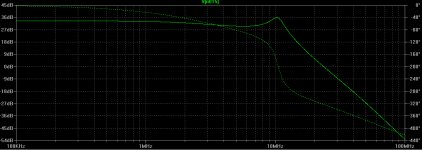
A stability question: I checked a closed loop bode with the version you sent, this is the 1st picture.
As I know with this -208° @ 0dB is not stable, right?
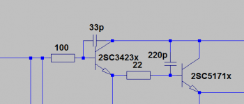
Anyway, this RC filtering @ OPS was just an idea, my OPS contains now only the 33pFs @ the pre-driver stage.
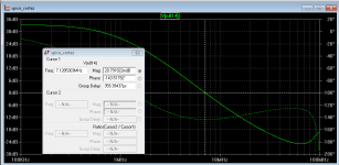
I made a bode with this setup as well, this is the 2nd picture.
Now @ 0dB the phase is -140° which is better and already stable, right?
But the compensation part looks good, I'll try it in reality hopefully in the evening!
The other issue: I have to be careful due to the underhand local OPS instability caused by these ultrafast drivers...
Hopefully I can check your compensation scheme without modding the whole OPS for a check...
And how did you get to this layout finally? What was the process?
(It's still not clear to me how to start/finish this compensation thing in the amp building process...)
A stability question: I checked a closed loop bode with the version you sent, this is the 1st picture.
As I know with this -208° @ 0dB is not stable, right?
Anyway, this RC filtering @ OPS was just an idea, my OPS contains now only the 33pFs @ the pre-driver stage.
I made a bode with this setup as well, this is the 2nd picture.
Now @ 0dB the phase is -140° which is better and already stable, right?
But the compensation part looks good, I'll try it in reality hopefully in the evening!
The other issue: I have to be careful due to the underhand local OPS instability caused by these ultrafast drivers...
Hopefully I can check your compensation scheme without modding the whole OPS for a check...
And how did you get to this layout finally? What was the process?
(It's still not clear to me how to start/finish this compensation thing in the amp building process...)
Attachments

I couldn't stand it and tried in reality quickly... 🙂
I have some oscillation but I guess its due to the OPS problems...
But otherwise the oscillation modulated result is looking good..! 🙂
(I couludn't take a picture due to the smoking current limiting resistors...)
Is there a way to separeate the OPS/IPS oscillation?
I mean: how can I know that an oscillation is casued by some OPS issue or from an improper IPS compensation?! 🙄
Other thing: as checked with CL bode this setup can not be stable without (< 22pF) the input filter cap, right?
Is this a bad thing or nothing wrong and acceptable?
Last edited:
- Status
- Not open for further replies.
- Home
- Amplifiers
- Solid State
- Heatsink vs OS stability