Finally I could set the current carefully.
Another question: one of the channels generates some whistle during switch-off.
What can be the cause? Is there a chance to eliminate it?
Another question: one of the channels generates some whistle during switch-off.
What can be the cause? Is there a chance to eliminate it?
Finally I could set the current carefully.
Another question: one of the channels generates some whistle during switch-off.
What can be the cause? Is there a chance to eliminate it?
Can you characterize the whistle in more detail. For instance does it rise in volume initially after switch off and level briefly before decaying or does it taper off uniformly from the initial level.
I suggest hooking up your oscilloscope to spot any behavioral differences between the two channels at switch off.
Finally I could set the current carefully.
Another question: one of the channels generates some whistle during switch-off.
What can be the cause? Is there a chance to eliminate it?
Oscillation.
Finally I could set the current carefully.
Another question: one of the channels generates some whistle during switch-off.
What can be the cause? Is there a chance to eliminate it?
Unity gain Xover point and phase margin change as the rails collapse.
Actually observed this on amps that I brought to the edge of stability for performance.
Overcompensation and more input stage degeneration (lower X-over /more margin)
solves this.
OS
Unity gain Xover point and phase margin change as the rails collapse.
Actually observed this on amps that I brought to the edge of stability for performance.
Overcompensation and more input stage degeneration (lower X-over /more margin)
solves this.
OS
@ Cortez,
You will recall also that the quiescent current level increases 3 or 4 times after the amplifier is switched off - your post 179 refers. What is going on is that the gain of your feedback loop is at least one at a frequency where the phase has reached 180 degrees and it will oscillate.
The reason for this is that the feedback signal path is providing a signal of the right size and phase to generate the output without any other signal input.
I hope you can now see the connection between the two issues and take on board the need to improve stability margins as noted by ostripper and others in several earlier posts.
Last edited:
I attached the recorded whistle. (VLC can play it.)
Okay so everything is related to HF stability... 🙂
I was just wondering why just one channel does this after matching almost everthing.
Ok then I'll check the compensation vs switch-off noise...
Thanks guys!
Okay so everything is related to HF stability... 🙂
I was just wondering why just one channel does this after matching almost everthing.
Ok then I'll check the compensation vs switch-off noise...
Thanks guys!
Attachments
I attached the recorded whistle. (VLC can play it.)
Okay so everything is related to HF stability... 🙂
I was just wondering why just one channel does this after matching almost everthing.
Ok then I'll check the compensation vs switch-off noise...
Thanks guys!
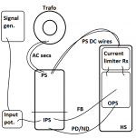
What do you think happens with your dc correction elements - presumably single IC based, one per channel - when you switch off? The observed phenomenon could be related to supply decoupling (possibly not equal decay of power supply rails) and some extraneous artefact from this cause being injected into the nfb line and triggering the noise action.
Last edited:
I attached the recorded whistle. (VLC can play it.)
Okay so everything is related to HF stability... 🙂
I was just wondering why just one channel does this after matching almost everthing.
The almost everything in terms of matching excludes your LTP which ideally needs to see similar impedances at the non-inverting and inverting inputs.
If you are going to reduce the impedances at the inverting terminal by a factor of ten then dc anomalies at the output are not to be unexpected.
The notion you are clinging to of benefits with low feedback resistor networks may have no effect in amplifiers having fully matched halves since the dc from one half should cancel the other.
You have incorporated a dc servo circuit to by way of compensating your more common LTP, however the purpose of these is to contain dc output drift. I assume there is a connection from the output of your power amp to the dc servo - it is not depicted this way in your circuit diagrams.
With regard to the power off whistle you might consider the possibility that one or other amplifier has greater dc offset without dc servo correction.
Measuring would be possible by snipping the connecting 2k resistor lead to the inverting terminal of the power amp at an angle of 45 degrees. It would be an easy task to match the faces to remake solder the connection .
Hi!
As reported earlier this amp is maybe on the edge of stability and that is still the case.
I used it for a while but a few weeks ago I took it to a friend to a comparison
and there was a diy DAC in the system without filter and maybe that was the cause
but my amp started to oscillate and went extreme hot in a couple of seconds...
I was surprised and of course disappointed a bit because I thought it's already stable...
Then we switched to a factory made CD player and it worked for a few minutes
but then one of the channels went off... I checked it right now and one of the output BJT-s
is a short circuit now...
So my question would be:
How can I test 100% sure the stability..?
What kind of things should I simulate both at the input and output?
Please dont think I didnt test it at all.
I stressed it with low resistive values down to 1R
and capacitive loads up to 22uF @ large output levels.
But as it seems this is not enough...
The only thing came to my mind that (if I remember correctly) there was
some (not fatal) oscillation with capacitive load around 10-20nF.
And finnaly I didnt build in an output inductor it seemed not neccesary based on my tests with these loads...
When the oscillation happaned there was nothing exotic in the system (except this diy DAC maybe...)
so the speakers were normal 2 way dynamic ones and the cable was a very thick 2x2 wire few meters long...
Thanks in advance for any help...!
No one..? 😱
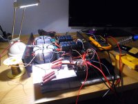
In the meantime I started to disassamble the amp.
I replaced the failed OS trany and now it's working again but with this messy
layout even when I start to set the OS quiescent current, it starts to oscillate.
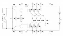
I attach the real layout and my OPS as well. The rails now have some current limiting resistors.
With these local decaps @ OPS do the PS rail wires lengths still matter?
I can increase the current to around 10-15mA and then the oscillation comes.
As I noticed near this point the amp is sensitive to my hand via the DMM wires
measuring the OPS emitter resistors for Iq but nothing else (FB, drive, PS...).
Otherwise with Iq = 0mA it's working and there is a good looking signal
when it's driven by a signal generator up to 100kHz square wave, etc...
How can I debug where (IPS/OPS) this oscillation is originally created?
Does it mean something that it only comes in when I increase the Iq?
Or this can also be caused by an improperly compensated IPS..?
In the meantime I started to disassamble the amp.
I replaced the failed OS trany and now it's working again but with this messy
layout even when I start to set the OS quiescent current, it starts to oscillate.
I attach the real layout and my OPS as well. The rails now have some current limiting resistors.
With these local decaps @ OPS do the PS rail wires lengths still matter?
I can increase the current to around 10-15mA and then the oscillation comes.
As I noticed near this point the amp is sensitive to my hand via the DMM wires
measuring the OPS emitter resistors for Iq but nothing else (FB, drive, PS...).
Otherwise with Iq = 0mA it's working and there is a good looking signal
when it's driven by a signal generator up to 100kHz square wave, etc...
How can I debug where (IPS/OPS) this oscillation is originally created?
Does it mean something that it only comes in when I increase the Iq?
Or this can also be caused by an improperly compensated IPS..?
Attachments
Last edited:
0r18 for emitter resistors could be a bit low for a 60V supply rail.
Have you checked output thermal stability using R.Cordell's guide?
Have you checked output thermal stability using R.Cordell's guide?
Sajti: I'll take out the whole PS/IPS section just now so the layout will change, I'll share it when it's ready!
Andrew: 0R18: Yes, it looked okay when it was not oscillating. I tried even with heavy dummy load for hours.
But untill then a few question:
Andrew: 0R18: Yes, it looked okay when it was not oscillating. I tried even with heavy dummy load for hours.
But untill then a few question:
- Okay the layout is esential but beyond that for a temporary debug situation can we state that an amp should
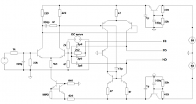
be stable with long (~20cm but twisted) PS wires as well (in case when local decaps are used just as attached)? - As I remember I couldnt stabilize it properly without the input cap (< 68pF) either... It should be?
So the input cap is just for HF filtering and it should not take any part in the stabilisation? - The same question for the output inductor: it is just an "extra" protection against heavy capacitive load
but the amp itself should be stable without it, right? - How can I debug where (IPS/OPS) this oscillation is originally created?
- As I remember I couldnt set any quiescent current @ OPS because of oscillation.
Is this normal after a certain level or even a class A state should be just a question of cooling but nothing else..? - The original question: after it seems okay on this "debug" layout: how could I test the stability with 100% certainity?

Hmm, now I could set the OPS Iq nicely up to 100mA (current limitation resistors
are getting hot so) and only then it started to oscilalte but even then just with a 1Vpp "sinus"...
Now the input filter is 1k-220pF. I tried without the 220pF but then it's oscilalting immediately on switch-on...
are getting hot so) and only then it started to oscilalte but even then just with a 1Vpp "sinus"...
Now the input filter is 1k-220pF. I tried without the 220pF but then it's oscilalting immediately on switch-on...
I would not remove the input filter completely.
Try reducing it by a factor of 5 to 10, i.e. use 22pF, or 47pF, instead of 220pF
But 1k0 & 220pF is quite high already. Does it need to be that high (F-3dB ~700kHz)?
Try reducing it by a factor of 5 to 10, i.e. use 22pF, or 47pF, instead of 220pF
But 1k0 & 220pF is quite high already. Does it need to be that high (F-3dB ~700kHz)?
Last edited:
But 1k0 & 220pF is quite high already. Does it need to be that high (F-3dB ~700kHz).
Be careful, because there is a passive volume control at the input! It may reduce the bandwidth
Sajti
Yes, there is a 10k volume pot at the input and there is no DC blocking cap.
Now I started to experiment with increasing the current compensation Cs.
Increasing the values with || 6p8 on the caps from OUT and VAS to FB point
helped a bit but a 22pF on already caused initial oscillation...
How can one know whether this is originated in the IPS or OPS?
Or the OPS layout looks OK and we can exluse it in this process?
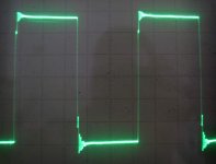
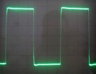
1st MOD:
Results (100kHz @ 0.5V/DIV):
Iq @ OPS = ~50mA
How to continue now...? Should I take out the input C while stabilizating the amp or not?
- extra 6p8 || on 3p9 on VAS+ (PD)
- extra 6p8 || on 3p9 on FB resistor (2k2)
Results (100kHz @ 0.5V/DIV):
- with no input cap
- with 10pF indput cap
Iq @ OPS = ~50mA
How to continue now...? Should I take out the input C while stabilizating the amp or not?
Attachments
- Status
- Not open for further replies.
- Home
- Amplifiers
- Solid State
- Heatsink vs OS stability