

you have the capacitors at the ends of leads that share the charging pulse currents with the DC currents to the amplifier.
The input (charging) lead must be separate from the exit lead to the amplifier.
The common part (shared) of the capacitor lead must be as short as possible.
It's an extension of this rule that gives Jensen and others the market to make and sell 4 lead capacitors.
The input (charging) lead must be separate from the exit lead to the amplifier.
The common part (shared) of the capacitor lead must be as short as possible.
It's an extension of this rule that gives Jensen and others the market to make and sell 4 lead capacitors.
Last edited:

you have the capacitors at the ends of leads that share the charging pulse currents with the DC currents to the amplifier.
The input (charging) lead must be separate from the exit lead to the amplifier.
The common part (shared) of the capacitor lead must be as short as possible.
It's an extension of this rule that gives Jensen and others the market to make and sell 4 lead capacitors.
I see this done regularly throughout the whole amplifier circuit. Everyone seems to be anal about star grounding but don't care about proper feed path. To me one should be as important as the other.
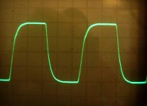
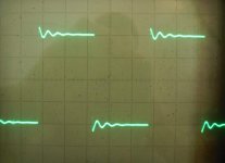
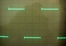
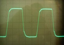
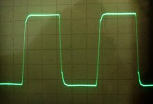
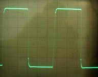
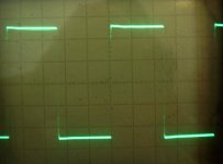
And finally the results (all @ 5V/DIV) with the schematic posted above:
I guess the last 2 would be even better with an ideal PS... 😉
- 20kHz
- 100kHz
- 200kHz
- 400kHz
- 1kHz || 2u2
- 10kHz || 2u2
I guess the last 2 would be even better with an ideal PS... 😉
Attachments
I see you are sticking with the lower value resistors in the negative feedback line which obviously reduces the impedance seen by the feedback signal. There are a couple of feedback capacitors from the voltage stage of 4.7p whose purpose is to bypass the output stage. When you rescale resistors down in value like this you need to compensate by increasing the bypass capacitance so the impedance relationship is maintained. You seem to be experimentally inclined so I will leave you to your own devices on that point.
Another point is that the gain bandwidth product of an amplifier is a finite quantity and if the amplifier is compensated for a certain stability margin for a given closed loop gain, something has to give should a decision be made to increase the closed loop gain. If the compensation remains unchanged then the stability margin will reduce. I note the presence of a trim pot in parallel with the lower arm resistor in your feedback arrangement which allows some albeit minor adjustment of closed loop gain.
This leaves you with some other scope for experimenting - to reduce closed loop gain in the interests of improved stability.
Last edited:
I dont have any trims there. There is only the OPS bias finally.
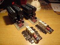
Meanwhile I brought the 2nd channel alive as well.
I attach the final sch for the values after the final adjustments:
HF: 3 x 3p9 + 330pF-47R + 47p
With 1k-82pF @ input the signals are a bit more smoother.
BTW: I'm very confident with these results thanks for all the members here for helping...!!!
Final amp assembly starts tomorrow... 😉
And of course looking fwd to the sound... 🙂
Attachments

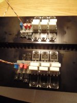
I am just at the final assembly phase and tried both channels and to setup the OPS bias precisely but I
got a bit strange behaviour with the bias. As you can see its just a simple Vbe multiplier with a 1k helitrimmer.
I used this type of soultion with success before but now its hard to setup the wanted current.
As I slowly turn it the current doesnt change then its starts but not linear then sometimes it decreases
even if I turn it further and things like that...
Meanwhile the output is watched on the scope and there is nothing oscillation or things like that, its dead quiet.
Can this because of the 3P OPS? I never had such effect earlier with 1P 2P... Also this type of devices are new to me (NJW).
Please help! 🙂
Last edited:
I am just at the final assembly phase and tried both channels and to setup the OPS bias precisely but I
got a bit strange behaviour with the bias. As you can see its just a simple Vbe multiplier with a 1k helitrimmer.
I used this type of soultion with success before but now its hard to setup the wanted current.
As I slowly turn it the current doesnt change then its starts but not linear then sometimes it decreases
even if I turn it further and things like that...
Meanwhile the output is watched on the scope and there is nothing oscillation or things like that, its dead quiet.
Can this because of the 3P OPS? I never had such effect earlier with 1P 2P... Also this type of devices are new to me (NJW).
Please help! 🙂
Since the amplifier appears stable you might measure the voltage across your V.be multiplier.
If you used the resistor values for an EF2 it is likely all the adjustment comes in a narrow band at the maximum end of your adjustment range, and, possibly that the range of adjustment is not enough to turn the 3 stage cascade on sufficiently.
With 3 diode junctions in the forward path of each EF3 half, the V.be will need to be capable of generating >3.6 volts.
If you are looking for a circuit with that capability, I would recommend checking out the scheme devised by Prof. Marshall Leach for his fully balanced EF3. There is a detailed discussion at http://users.ece.gatech.edu/mleach/lowtim/
25 years ago I built an early version of this project. Setting the V.be is an easy adjustment, and a set and forget one at that.
Last edited:
I already used this with an EF3 as well. BTW: tried it this morning again and adjusting it carefully makes it work now...
I let the temperature set a bit for a few minutes after switch on and I even after that just turned the pot slowly.
Maybe yesterday there was some overheating due to a higher Iq current and thats what tricked me during the temperature settling...
I let the temperature set a bit for a few minutes after switch on and I even after that just turned the pot slowly.
Maybe yesterday there was some overheating due to a higher Iq current and thats what tricked me during the temperature settling...
I already used this with an EF3 as well. BTW: tried it this morning again and adjusting it carefully makes it work now...
I let the temperature set a bit for a few minutes after switch on and I even after that just turned the pot slowly.
Maybe yesterday there was some overheating due to a higher Iq current and thats what tricked me during the temperature settling...
There should not be any creep in Iq once the setting is made and the adjustment should be smooth without an avalache effect at any point in the range of adjustment where Iq increases exponentially.
If this is your experience, the heating may be due to an issue of marginal stability of your feedback loop, causing mutual conduction in the output stage. In that case the trimpot to adjust Iq would act as a restraint until the point of conduction is reached where the feedback loop comes into play.
Picture marginal loop stability as analagous to a car parked on a steep incline and mutual conduction to gravity. The hand brake is on full but the car creaks when you move to open the door to get out.
Okay and what should I check or do now to make it work smoothly?
I suggested Marshall Leach's V.be multiplier as useful in circuits that do away with constant current sources or substitute current mirrors.
Re: loop stability, suggestions were made by members who had developed EF3 circuits, namely ostripper and bonsai, and I think you should review these, particularly posts #59 and #60.
A simulation of your circuit as it was at the time indicated a problem at 2.8MHz, leading to the suggestions, the limit for an EF3 stage was 1.5MHz and your MIC (Miller Inclusive Capacitor) of 10 pF was low in relation to the need. Earlier, in post #4, campsquire's approximation was 1MHz and you needed to reduce the closed loop gain beyond 100 kHz.
You can plug in different values of MIC capacitor (or other capacitors) to see what works, or enquire of ostripper whether his SPICE file will work with a free version of that software, and if he would share his file with you to work on.
No, it can be adjusted just in a tricky way but I still dont know why... 😱
If its possible I wouldn't change the schematic as a first step.
And I don't see at all how the loop stability is related to this issue anyway.
As I said the amp is stable and I already used the same topology with 1P and 2P OPSes without this phenomena.
I dont know whether its because of 3P OPS or something else...
I used a differenct type of trimpot at the Vbe so maybe I should check that as well.
And "measure the voltage across your V.be multiplier" as you just recommended earlier to see the problem is before or after this point...
The Vbe itself can generate the neccesary voltage but the adjustment process is strange: when I turn the pot it doesnt reply for a while
then it jumps and the same in the opposite direction as well. Nobody had a similar issue with the bias yet?
And another thing: if I set a current value somehow it remains stable during use but after a switchin off and on again it jumps to a 3x/4x
higher value as a start then it starts to decrease but if I remember correctly it doesnt decrease to the level I set up but a bit higher... 🙄
No, it can be adjusted just in a tricky way but I still dont know why... 😱
If its possible I wouldn't change the schematic as a first step.
And I don't see at all how the loop stability is related to this issue anyway.
As I said the amp is stable and I already used the same topology with 1P and 2P OPSes without this phenomena.
I dont know whether its because of 3P OPS or something else...
I used a differenct type of trimpot at the Vbe so maybe I should check that as well.
And "measure the voltage across your V.be multiplier" as you just recommended earlier to see the problem is before or after this point...
The Vbe itself can generate the neccesary voltage but the adjustment process is strange: when I turn the pot it doesnt reply for a while
then it jumps and the same in the opposite direction as well. Nobody had a similar issue with the bias yet?
And another thing: if I set a current value somehow it remains stable during use but after a switchin off and on again it jumps to a 3x/4x
higher value as a start then it starts to decrease but if I remember correctly it doesnt decrease to the level I set up but a bit higher... 🙄
It would be instructive to know you can detect any a.c. voltage on the collector of the V.be transistor with your oscilloscope.
I came across a link on the issue V.be stability while searching for information about the Symasym amplifier.
I did not make note of where, however you might try fitting a 100n capacitor (like a Miller capacitor) between collector and base of the V.be transistor.
Let me know how you get on.
- Status
- Not open for further replies.
- Home
- Amplifiers
- Solid State
- Heatsink vs OS stability