About slew rate and VAS: its still not clear to me.
Whats the difference @ VAS between a VFA and CFA?
In open loop the input stage drives the VAS with a high level signal untill
the FB reduces it via the FB, right? Why is a VFA then slower @ the VAS?
Whats the difference @ VAS between a VFA and CFA?
In open loop the input stage drives the VAS with a high level signal untill
the FB reduces it via the FB, right? Why is a VFA then slower @ the VAS?
About slew rate and VAS: its still not clear to me.
Whats the difference @ VAS between a VFA and CFA?
In open loop the input stage drives the VAS with a high level signal untill
the FB reduces it via the FB, right? Why is a VFA then slower @ the VAS?
VFA is usually assumed to have an LTP input pair that has a limited output current (maxing out at tail durrent) to charge/discharge the miller cap and Ccb of a VAS stage, while in the CFA topology such limitation is removed, and the charge/discharge current to the said capacitance being (error) signal amplitude dependent can be much larger than the tail current in an LTP. This is why they differ in slew behavior.
Last edited:
Perspective, not "persecution"
Cortez - you should be aware that there are some CFA "fanboys" - attributing advantages to CFA topology that are irrelevant at best, and claiming some not unique to CFA
Esperado posted a sim that simply won't run in a clean install of LTSpice - and keeps pointing to it, after I have warned, even reworked it with all of the needed models
of course I also included a VFA circuit sim with the same Q count and order of magnitude better performance
the "speed" advantage of CFA is marginal when everyone has to use the same relatively slow power output Q - they are the real limit not the front end topology
so don't be steamrolled by the fanboys - several of my posts illustrating their "CFA is Superior" claims' overreach use a sim of Cordell's Error Correction Mosfet Power Amp from 1983 - it really doesn't look like the CFA fanboys have stumbled on a "magic formula"
there are tradeoffs, but we are in the position of now having devices, topologies and circuit understanding to make competent audio power amps with a variety of approaches
and the subjective evidence in controlled listening test doesn't pick out any one approach as "night and day" superior - they can't even be told apart reliably in ABX with US$10k on the line
Last edited:
looks like "the same number of Q" referred to the diff pair strawman circuit put up by the "CFA fanboy"
http://www.diyaudio.com/forums/solid-state/240712-cfa-topology-audio-amplifiers-73.html#post3615032
http://www.diyaudio.com/forums/solid-state/240712-cfa-topology-audio-amplifiers-73.html#post3615032
the "speed" advantage of CFA is marginal when everyone has to use the same relatively slow power output Q - they are the real limit not the front end topology
Modern output transistor like 2sc5200 won't be slowest device in the loop.
Input Stage contributes the 2nd pole in the loop gain. (1st pole is set by miller capacitor)
The limit is the front end, unless you prefer some vintage transistors as output / drivers.
there are tradeoffs, but we are in the position of now having devices, topologies and circuit understanding to make competent audio power amps with a variety of approaches
and the subjective evidence in controlled listening test doesn't pick out any one approach as "night and day" superior - they can't even be told apart reliably in ABX with US$10k on the line
That's true, there are some tradeoffs. LTP is more linear without any argue, and "slew rate" never be be bottle neck in sound system.
The negative input section in CFA topology is common-base configuration. It will be much faster than LTP's common-emitter configuration, but it will lose some linearity.
PS: I am not a fan boy of CFA. All the amplifiers I made are VFA, none of those are CFA, although I tried some in the simulation.
Last edited:
I played around with this symasym topology and I have to say its a really great one.
It also has a very good slew rate (as you can see on the previous picture) and sounds good as well.
If I had adjustable caps I could trim it to its best but even with standard values it performs good up to 3-400kHz like a SlewMaster/CFA.
It also has a very good slew rate (as you can see on the previous picture) and sounds good as well.
If I had adjustable caps I could trim it to its best but even with standard values it performs good up to 3-400kHz like a SlewMaster/CFA.
Thanks jcx, I'll check it out..!
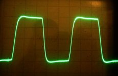
And today's result: my (VFA?! 🙂) symasym amp @ 400kHz 20Vpp (no load)... 😎
Can you post a scope image for a square wave @10kHz 20 Vpp into 8R//2uF.
I'll try it for you on my prototype (the final amp is already in a "closed" stage at last... 🙂)
BTW I usually do my C load tests with 1kHz. With 10kHz || 2uF it will have definetely a poor output and maybe lot of ringing... 😱
Prototype means OPS with 1P trannies and with a smaller PS (less filter caps).
BTW I usually do my C load tests with 1kHz. With 10kHz || 2uF it will have definetely a poor output and maybe lot of ringing... 😱
Prototype means OPS with 1P trannies and with a smaller PS (less filter caps).

I didnt wanted to ruin my prototype so there were some protection resistors series with the main DC rails.
This is 10kHz 2V/DIV. The load was 1uF without R.
With higher output levels the amp collapses... 😱
(1k - 22pF @ IP, no coil @ OP...)
Just wondering from the reference to Symasym whether the prototype still has an EF3 stage as projected or have you changed it to an EF2.
A 1uF capacitor on its own is not representative of a loudspeaker load. If you are concerned about avoiding damage to the prototype you could look at the wave-form on an 8R load and start with a small value parallel capacitor - say 100n.
A tentative approach would be to have a selection of capacitors available and have a momentary push switch in the test capacitor circuit and gradually increase the output signal strength. You can flick or hold down the switch depending on what you observe on the screen of your scope.
With regard to the absence of an output coil, the negative feedback line is also an amplifier input and it's purpose is to mitigate against load induced signals causing problems. Another approach is to fit a 0R22 resistor between the amplifier output and the load.
I am not suggesting this as a cure all, as there were no stability problems with your prototype as an EF2. An EF3 version would have introduced an additional phase shift in the forward signal path which would have reduced the stability margin as compared to the original.
Your "Human Touch" experience no doubt loaded the voltage amplifier stage with capacitance so the system gain would fall to one at a frequency further in advance of the feedback phase reaching 180 degrees - where break down would occur.
That problem has been a starting point for some of the input you have received which in theory should have addressed the issues except perhaps if there was one hidden within the output stage - the issue of decoupling has been discussed in this regard.
A few low key suggestions (Post#35, Post #72) have been made over fitting stopper resistors in transistor bases in each EF3 stage - that is 6 resistors. You will see some stopper resistors in the image in post #47 for the "Slew Master" amplifier.
You appear to have left these stones unturned.
The Marantz PM16 is an up market amplifier using EF3 with 6 stopper resistors.
The prototype has EF3 and decoupling and base stoppers as well.
And it is now stable. BTW: I played with these base stoppers and found that
(in may case) they are only needed @ the power transistors (4R7). Without
them I saw some small, local oscillations on the waveforms under heavy load.
So I dont have any at the predriver and driver stages now.
And the paralell caps (on Vbe and predrivers emitter resistor) looked also unnecessary to me.
About C load: usually I make my tests from 1nF to 33uF with 1kHz square wave but not with 10kHz ... 🙂
Did this explain the rest of your comments ?PS: I am not a fan boy of CFA. All the amplifiers I made are VFA, none of those are CFA, although I tried some in the simulation.
I don't agree (at all) with your assertion: "LTP is more linear without any argue."
http://www.esperado.fr/temp/VSSA/vssa-vs-vfa.html
And you forgot an important point: VFA are compressive, while CFAs are expansive.
I remarked that CFA fans always had build or used the two topologies, while VFA ones often had never experienced any CFA.
The prototype has EF3 and decoupling and base stoppers as well.
And it is now stable. BTW: I played with these base stoppers and found that
(in may case) they are only needed @ the power transistors (4R7). Without
them I saw some small, local oscillations on the waveforms under heavy load.
So I dont have any at the predriver and driver stages now.
And the paralell caps (on Vbe and predrivers emitter resistor) looked also unnecessary to me.
About C load: usually I make my tests from 1nF to 33uF with 1kHz square wave but not with 10kHz ... 🙂
Reading the argument over CFA and VFA led me to this thread http://www.diyaudio.com/forums/solid-state/240712-cfa-topology-audio-amplifiers-574.html from which I see that Robert Cordell has outlined methods to overcome problems with EF3 output stages.
Continuing for a few pages down I noted those methods been tested by Bonsai who contributes to discussions on this site. I was interested to visit his website to see he has looked into CFA and VFA topologies, amongst other things.
BTW: what can be read from a wave form like above?
Thr squarewave is 10kHz and the ringing is about 100kHz.
Thats would be the final bandwith..?
Thr squarewave is 10kHz and the ringing is about 100kHz.
Thats would be the final bandwith..?
BTW: what can be read from a wave form like above?
Thr squarewave is 10kHz and the ringing is about 100kHz.
Thats would be the final bandwith..?
The wave forms you have posted in earlier stages of development are more the shape of what you would want to see. Unfortunately comparisons cannot be drawn if the test load used is subject to being changed and it is difficult to tell if we are moving in a forward or backward direction or one step forward and another step back. If you want to pick the differences you need 10 kHz as a test frequency;
It would be helpful to be able to see the latest update of the circuit diagram. Having looked at the versions posted I noted this circuit will amplify down to d.c. which I see as looking for trouble. Also in the image that accompanied post#70 on page 7, the bias transistor network has 300 ohm stopper resistors in series with the positive and negative voltage feeds, whereas they should remained connected to the voltage amplifier halves as per the image in post#33 on page 4. This change was unhelpful.
The stopper resistors should have been taken from the bias transistor collector and emitter connections to the bases of the first driver stage transistors. I would have suggested lower value resistors - 100 ohms perhaps.
You have shown an 8 ohm resistor in parallel with the output zobel network it is not clear whether this represents the speaker load or an added component - presumably the first.
To convert from a d.c. amplifier you would need a capacitor in series with the 1k resistor that decouples the lower arm, of the negative feedback dividing network, to the earth line. You could try 100 uF polarized according to the voltage at the junction seen at the top of the 1k resistor.
Last edited:
Here it is...!
(The C multiplier its just for later versions, not tried yet...)
What's not shown on this schematic is the PS for OPS and the output coil.
PS has decoupling C-s with RC for pre/driver stage and the
outpout coil is 13 turns 12mm with dia || 10R 5W wirewound.
(The C multiplier its just for later versions, not tried yet...)
What's not shown on this schematic is the PS for OPS and the output coil.
PS has decoupling C-s with RC for pre/driver stage and the
outpout coil is 13 turns 12mm with dia || 10R 5W wirewound.
Attachments

Did this explain the rest of your comments ?
I don't agree (at all) with your assertion: "LTP is more linear without any argue."
http://www.esperado.fr/temp/VSSA/vssa-vs-vfa.html
Yes, what I said may be too bold. There are few exceptions you can find depends how it is implemented.
In the link you provided, the CFA configuration is just 2 single end input stages coupling together. One works for positive cycle, the other works for negative cycle. The VFA configuration is 2 LTPs coupling together. There is no chance that single end input will be more linear than differential input.
BTW, these 2 cases are not identical in open loop bandwidth, which related to how much available feedback you will get, and there are lots of things can contribute low THD, e.g. slew rates and low latency on negative feedback pin. And don't forget it is in simulation. In reality, it is hard to use PNP to cancel out the un-linearity of a NPN. It makes more sense to use a pair of same type of device to cancel out their un-linearity.
Last edited:
Here it is...!
(The C multiplier its just for later versions, not tried yet...)
What's not shown on this schematic is the PS for OPS and the output coil.
PS has decoupling C-s with RC for pre/driver stage and the
outpout coil is 13 turns 12mm with dia || 10R 5W wirewound.
Before addressing this in too great detail what is the voltage reading on the speaker output terminal and what is the voltage drop across any of the power device emitter resistors?
Direct current amplifiers are known to drift with temperature so it will be worth monitoring the variation according to ambient conditions over a day or so.
I note the absence of any trim pots to make any adjustment for this and output stage quiescent current.
- Status
- Not open for further replies.
- Home
- Amplifiers
- Solid State
- Heatsink vs OS stability