You are picking up the "filth" of the 21st century.
Most likely your PC. Harmonics of cheap chinese CFL , other
cheap SMPS's can cause this RF hash , as well.
For your audio , filter across the ground loop breaker and/or
an AC input filter.
OS
Most likely your PC. Harmonics of cheap chinese CFL , other
cheap SMPS's can cause this RF hash , as well.
For your audio , filter across the ground loop breaker and/or
an AC input filter.
OS
Sorry I moved my post to the HUM thread (its not related to stability rather some wiring I guess.)
I'll quote this there...
I'll quote this there...
About the HF comp caps: what's the rule to using a series R with these caps?
What they do here and how the value should be applied?
What they do here and how the value should be applied?
Just reporting some mods and results maybe it will be useful for others:
- decoupling caps + base stoppers @ OPS (copying the SlewMaster OPS)
result: stable OPS of course... 🙂
extra experiments: on my prototype I started to take out the parts one by one to see which one is maybe
unnessecary and for me the base stopper seems to be but I'll do some further tests around this topic... - HF compensation: the final and best results now are with: 2 x 10pF from VAS both output to INV input + 33pF
(in place where the 100pF is @ the MikeB symasym)
result: nice slewrate and square waves up to 2-300kHz and together with the OPS mods now the input is less sensitive so with a
22pF input cap even with my extreme noisy PC source its now stable (earlier this caused an oscillation at higher pot levels...) - emitter degeneration (recommended by OS) with a 100R trimmer
result: in my case no improvement - output coil (13 turns || 10R 5W wirewound)
result: before the output was instable with pure and low C (1-47nF) load with this its now stable
but with capacitive load when watching the point after the coil (at the cap legs) the voltage swing
at the ringing is higher then without the coil... is this normal..?
side effect: the coil is (hum) sensitive to the EMI so I had to shield it around with a piece of trafo base material tape
Last edited:
Could someone please enlighten me about the function/effect of the caps usually put in an OPS || @ Vbe bias and driver common emitter R?
Like C108 and C114 here:
http://startfetch.com/ostripper/docs/Slewmonster-OPS/SLEWMASTER2-P-V1.2/Slew-main-schema.gif
My questions:
Or it is usually applied just as a rule of thumb without any evidence..?! 😀
Like C108 and C114 here:
http://startfetch.com/ostripper/docs/Slewmonster-OPS/SLEWMASTER2-P-V1.2/Slew-main-schema.gif
My questions:
- now (I think... 🙂) my OPS is OK without them, what should I check (on scope) or hear with an AB test with/without them..?
- what are the values based on
- in an EF3 why it is usually "missing" @ the predriver emitter R?
Or it is usually applied just as a rule of thumb without any evidence..?! 😀
Could someone please enlighten me about the function/effect of the caps usually put in an OPS || @ Vbe bias and driver common emitter R?
Like C108 and C114 here:
http://startfetch.com/ostripper/docs/Slewmonster-OPS/SLEWMASTER2-P-V1.2/Slew-main-schema.gif
My questions:
- now (I think... 🙂) my OPS is OK without them, what should I check (on scope) or hear with an AB test with/without them..?
- what are the values based on
- in an EF3 why it is usually "missing" @ the predriver emitter R?
Or it is usually applied just as a rule of thumb without any evidence..?! 😀
C108 is necessary, C114 is optional.
I recommend to keep C108, and remove C114.
About the value, 0.1uf/0.01uf ceramic will do. Don't put film or cylinder cap.
Here is the details.
C108 serves as high frequency bypass route. It bypasses 'bias network' at very high frequency, at which point, Q103 and Q104 are not fast enough to regulate the bias voltage. 0.1uf is well enough. 0.01uf is even better, here is not 'the bigger the better', big cap will slow down the regulation effect of Q103 and Q104.
The reason I suggest remove C114 is that, the driver stage may work in class AB mode. If there is cap like C114 there, charging speed will be faster than discharging, the voltage trapped inside the Cap will be reluctant to be fully discharged, which will cause output transistor over biased. This will happen when amplifier operated under high frequency / high dynamic signal.
Could someone please enlighten me about the function/effect of the caps usually put in an OPS || @ Vbe bias and driver common emitter R?
Like C108 and C114 here:
http://startfetch.com/ostripper/docs/Slewmonster-OPS/SLEWMASTER2-P-V1.2/Slew-main-schema.gif
My questions:
- now (I think... 🙂) my OPS is OK without them, what should I check (on scope) or hear with an AB test with/without them..?
- what are the values based on
- in an EF3 why it is usually "missing" @ the predriver emitter R?
Or it is usually applied just as a rule of thumb without any evidence..?! 😀
I am not sure which R your are talking about in your hyperlink.
All R @ emitter of predriver/driver/output transistor are used to set correct bias current for the transistor. Normally, they cannot be omitted.
There is one thing very important for EF3. Base stopper resistor cannot be omitted in EF3 output.
Emitter follower cannot handle inductive input well. Inductive input from base pin with the Parasitic Capacitance on the transistor is a very good formula to produce ringing. Unfortunately, the output of emitter follower is inductive. The output current comes from EF is reluctant to change immediately. It's really hard to explain this in 2 or 3 sentences, but trust me for now. The output of EF is inductive, so if you cascading EFs together, it will ring. Base stopper resistor is the way to solve this. It provides damping factor which is very important for EF3.
Thanks jxdking!
and its working even @ 1-200Hz square I dont see any special error.
What should be spot in a before/after test on the scope?
And how can I AB test it? As I said in my OPS currently there is no C thereC108 is necessary, C114 is optional.
and its working even @ 1-200Hz square I dont see any special error.
What should be spot in a before/after test on the scope?
I meant the R110. If there is a C @ R113 why isnt there on R110?I am not sure which R your are talking about in your hyperlink.
It's not so hard: because the internal Cs are charged it will remain opened untill this charge is discharged via the B pin, right?It's really hard to explain this in 2 or 3 sentences, but trust me for now.
Thanks jxdking!
And how can I AB test it? As I said in my OPS currently there is no C there
and its working even @ 1-200Hz square I dont see any special error.
What should be spot in a before/after test on the scope?
C108 works as seat belt on your car. If you don't wear it, you won't die immediately.
I remember there was a thread in the forum, someone encountered some strange stability issue because of this capacitor. Also you can find related topic in Douglas's Audio Power Amplifier Design Handbook.
The cap here and C114 are both optional, at least I don't see any point to keep them in, as long as Q103 and Q104 get bypassed with C108 .I meant the R110. If there is a C @ R113 why isnt there on R110?
It's not so hard: because the internal Cs are charged it will remain opened untill this charge is discharged via the B pin, right?
YES, that's exactly what I am trying to say. 😀
This?
http://www.diyaudio.com/forums/solid-state/234408-stability-analysis-ef-output-stages.html
So if I dont have any similar oscillation all of them are unnecessary...?!
http://www.diyaudio.com/forums/solid-state/234408-stability-analysis-ef-output-stages.html
So if I dont have any similar oscillation all of them are unnecessary...?!
This?
http://www.diyaudio.com/forums/solid-state/234408-stability-analysis-ef-output-stages.html
So if I dont have any similar oscillation all of them are unnecessary...?!
Yes, that's the thread.
Even if you don't have this issue, I still suggest to keep C108 in. It will give you extra safety margin. As I said, it works like a seat belt. You may not drive faster when you wear seat belt, but it will keep you safe when bad things happen.
Gain: yeah I am just experimenting with reducing all the local FB resistors at my IPS.That's a lot of gain. Most of us manage with 20times to 30times. You have 2k3 (not an E24 value) divided by 47r plus 1 = ~50times (+34dB).
What is the peak voltage across the 2k347 combination?
What is the peak instantaneous dissipation?
What is the distortion due to tempco?
Pmax: ~ 1W.
Distortion: I dont have exact measurements but @ low levels it shouldn't be much and
at really high P levels not this kind of distortion source will be the worse, I guess.
Are you using a 10W 2k3?Gain: yeah I am just experimenting with reducing all the local FB resistors at my IPS.
Pmax: ~ 1W...............
I recommend and many other similarly recommend that the NFB resistors are not subjected to powers that exceed 10% of their maximum rating.
That limits a 0.6W resistor to 60mW and a 1/8thW resistor would be limited to 12.5mW
Why are you applying 1W?
That limits a 0.6W resistor to 60mW and a 1/8thW resistor would be limited to 12.5mW
Why are you applying 1W?
I reduced my Rfb values based on this article (section "One remark"):
www.esperado.fr/temp/VSSA/vssa-vs-vfa.html
As a positive side effect my (~10cm long) IPS to OPS twisted pair wire is now much
less sensitive to any capacitive impact and the initial hum has gone away as well.
www.esperado.fr/temp/VSSA/vssa-vs-vfa.html
As a positive side effect my (~10cm long) IPS to OPS twisted pair wire is now much
less sensitive to any capacitive impact and the initial hum has gone away as well.
I reduced my Rfb values based on this article (section "One remark"):
www.esperado.fr/temp/VSSA/vssa-vs-vfa.html
As a positive side effect my (~10cm long) IPS to OPS twisted pair wire is now much
less sensitive to any capacitive impact and the initial hum has gone away as well.
For VFA, the input impedance of both + and - should be same value. I mean both AC impedance and DC impedance should appear to be same value at positive input pin and non-positive input pin. Otherwise it will suffer something like high DC output.
CFA has some good attributes.
1. CFA allows VAS (2nd stage) working in class AB push pull mode. That's why CFA can achieve amazing slew rate figures.
2. CFA uses low value Rfb, and low impedance on negative input pin doesn't contribute extra pole in the system. That means you can crank up Unit Loop Gain Frequency. That's why CFA normally has wider open loop bandwidth.
BTW, 10 cm is not a long trace. Normally it won't be a problem. And the square response looks not bad at all. Good job!
Last edited:
I dont have any high DC offset with this setup at all.
In the meantime I tried these paralell caps @ Vbe bias, and paralell on the emitter
resistors for the 1st 2 stages in the EF3 but without them the results are still great...
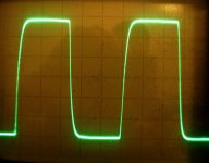
I used 100kHz 40Vpp test signal (without load) and watched the form of the square wave and the current at the emitter resistors...
In the meantime I tried these paralell caps @ Vbe bias, and paralell on the emitter
resistors for the 1st 2 stages in the EF3 but without them the results are still great...
I used 100kHz 40Vpp test signal (without load) and watched the form of the square wave and the current at the emitter resistors...
- Status
- Not open for further replies.
- Home
- Amplifiers
- Solid State
- Heatsink vs OS stability