I agree on all that I gave not edited out.1. Decouple the OPS rails right at the collectors (220uF in // with 0.1 film
2. Isolate your pre driver from driver stage with an RC network in the rail and a c 10 ohm in the collector of each driver. Also your driver damper network values need work. A more conventional network would be 27 ohms and 470 of from the driver base to the V+ Rail.
3. Your input filter fo is too high. It should be at 500 kHz or lower
4. Add a Zobel. Without it you are going to get problems
5 . You need an output L on a design like this OR a very low ULGF otherwise you will get problems
.......................
As OS has remarked, you need to work on above issues and only after that can you address hum problems
I don't know enough about item 6 to comment.
Separate MF & HF decoupling for the output devices. The traces must allow this.
Separate MF & HF decoupling between the drivers and predrivers. Again the traces must allow this.
RC isolation works very well with low values of R combined with high values of MF decoupling.
And use the full Thiele Network:
C+R from Output to Power Ground.
L||R from Output to speaker terminals.
Optional R+C across the speaker terminals, to add a Pi filter for further RF attenuation.
For bench testing the very low value of RF capacitor will allow fast signals to prompt and display output effects. Then revert to a normal RF attenuation capacitor value. I use ~700ns as RF attenuation, but change this to ~70ns for testing. You have 22ns of RF filtering in the sch.
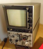
- I just bought my new (2nd hand HP 182A) scope so now I can measure whatever you just say! 🙂
- Could somebody please post an ideal scope output with a 0 hum and not oscilalting amp to see a normal noise level and spectrum as a reference?
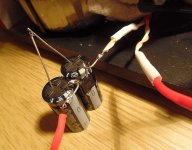
(I'll show my current state as soon as I learnt use this new device... 🙂) - I tried a DC blocker (2nd picture) just for curiousity but it didnt change anything.
- About the mods:
- OPS PS decoupling: ok!
- Pre-driver PS RC: 10R + 100uF?
- Input filter: I tuned it to produce a nice 100kHz squarewave @ output.
If there is no extra HF garbage should I increase the 22pF anyway..? - Zobel: there is a zobel at the schematic as well at end: 100nF + 4R7 or did you mean somewhere else..?
- Sorry: I left it out: I use a 0R3 wirewound 5W resistor (not a low inductance one of course... 🙂) series with the output
- ULGF: well I dont know, how it should be measured..? 🙄
AndrewT:
MF, HF = ?
Attachments
I guess then really I should follow ostripers layout:
http://startfetch.com/ostripper/docs/Slewmonster-OPS/SLEWMASTER2-P-V1.2/Slew-main-schema.gif
http://startfetch.com/ostripper/docs/Slewmonster-OPS/SLEWMASTER2-P-V1.2/Slew-main-schema.gif
Connect a load and drive it to c. 70 % of the rated output swing. Let's look at the waveform under these conditions.
Also, feed a square wave in and lets then also look at the output.
However we are no longer taking about hum here but about compensation . . .
Also, feed a square wave in and lets then also look at the output.
However we are no longer taking about hum here but about compensation . . .
Last edited:
You can hear-it. You can see-it, i told-you it was-it, so why to ask the question ?Is it oscillating...?
You're right I'll continue the HF part in the original thread and link it here if there is something suspicious...
(Maybe I ask a moderator to put these posts to that thread as well not to mix it here...)
(Maybe I ask a moderator to put these posts to that thread as well not to mix it here...)
You're right I'll continue the HF part in the original thread and link it here if there is something suspicious...
(Maybe I ask a moderator to put these posts to that thread as well not to mix it here...)
Keep your core design , but consider the decoupling. With a typical EF3 ,
you have about 5K current gain with pre and driver. Some only decouple
the pre-driver. (not enough)
The outputs multiply this by 30-70X for 100-300K total gain.
Better to have the bulk of this gain behind the R/C. PSRR goes
up >15db as a side benefit.
Most importantly , with that local FB loop eliminated - NO oscillation. 🙂
PS - you are most likely amplifying your PS ripple (as you have it now-hum)
Also .... fast/fast/ less fast (30mhz) for your three EF stages.
OS
I heard just a hum and some normal level white noise.You can hear-it. You can see-it, i told-you it was-it, so why to ask the question ?
What I see doesnt look like a classic oscillation just some extra HF ripple.
So I am asking because I am not sure it is an oscillation.
And no one confirmed it right now.
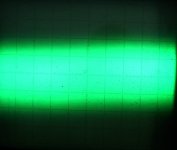
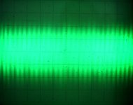
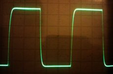
See my attach: 10kHz square wave 25Vpp @ 4R dummy load. Looks like oscillating?!
Could somebody show me a quiet amp output noise please as a reference?
(5mV/DIV 0.2ms/DIV and 0.2us/DIV)
Thanks!
Ok, thanks OS! Tomorrow I will buy the parts and try them on my OPS.Keep your core design , but consider the decoupling.
Should I "copy" the R & C values from your OPS as a start for my EF3 as well?
(http://startfetch.com/ostripper/docs/Slewmonster-OPS/SLEWMASTER2-P-V1.2/Slew-main-schema.gif)
If it helps my parts:
- Input & CCS: BC546B/BC556B
- VAS & Pre-Drivers: 2SA1360/2SC3423
- Drivers: 2SA1930/2SC5171
- Output: MJL3281A/MJL1302A
Attachments
Last edited:
This should be enough? Or the 22uF/device should be used as well?
And also the driver/output base stoppers have to be used for safety?
Caps on the pre-driver & driver emitter resistors?
(About the 300R resistors: I draw them on the wrong place on the prev picture, here they are now...)
And also the driver/output base stoppers have to be used for safety?
Caps on the pre-driver & driver emitter resistors?
(About the 300R resistors: I draw them on the wrong place on the prev picture, here they are now...)
Attachments
Last edited:
Cortez, had-ou removed the input filter to make your square waves measurements ?
Look both at them with high and little signals.
Look both at them with high and little signals.
You need add some base stopper resistors to pre-driver (100R), to driver (10R) and to output devices (4R7). Stopper resistors are importance.
Predriver's Ccb 47 to 100pF. 22pF seem a litle bit small.
Predriver's Ccb 47 to 100pF. 22pF seem a litle bit small.
post70.
I would move the 4r7 to the other side of the driver collector/s
If you retain that 4r7 then you need to also add the capacitance just next to it.
i.e. two sets of RC decoupling after feeding the main output devices.
I would move the 4r7 to the other side of the driver collector/s
If you retain that 4r7 then you need to also add the capacitance just next to it.
i.e. two sets of RC decoupling after feeding the main output devices.
No, the 22pF was still there @ input.Cortez, had-ou removed the input filter to make your square waves measurements ?
Look both at them with high and little signals.
Ok I'll look them, thanks!
BTW: already @ 10kHz 20Vpp my 3x2W zobel Rs were giving some smokey warnings.
Is this normal @ this frequency and load situation or is a clear sign of some HF oscillation maybe?
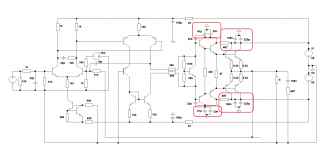
You mean using a 2 step RC on the rails like this:two sets of RC decoupling after feeding the main output devices
- main OP devices: 470uF+100nF + 22uF/device
- drivers: 4R7 + 47u+20nF
- pre-drivers: 4R7 + 47u+20nF
Last edited:
I think the fast current changes at the fast driver devices should be separated from influencing the Pre-Drivers.
Either two stages of RC, or one stage between Drivers and Pre-Drivers.
At the moment the relatively slower current changes of the Outputs are separated from the Drivers+Pre-Drivers.
Either two stages of RC, or one stage between Drivers and Pre-Drivers.
At the moment the relatively slower current changes of the Outputs are separated from the Drivers+Pre-Drivers.
Output Zobel should turn on @ 100kHz to 400kHz.............
BTW: already @ 10kHz 20Vpp my 3x2W zobel Rs were giving some smokey warnings.
Is this normal @ this frequency and load situation or is a clear sign of some HF oscillation maybe?.............
A 10kHz sqw has some content @ 100kHz but not enough to overheat the Zobel resistor.
A 50kHz sqw may overheat the Zobel resistor.
BTW, the internal ESR of the Zobel capacitor also does a good job of overheating the capacitor if the resistor is already overheating. i.e. change both if you have a oscillation incident.
Last edited:
That is still a very fast rise time for your input.No, the 22pF was still there @ input.............
You were told a long time back and I also gave some guidance to sizing the input filter.
No, it is not. The power rating of your Zobel resistance is not high enough ?BTW: already @ 10kHz 20Vpp my 3x2W zobel Rs were giving some smokey warnings.
Is this normal @ this frequency and load situation or is a clear sign of some HF oscillation maybe?
Of course, if you do some full level measurements at MHz, you will need to remove the Zobel if you don't want it to smoke, but at 20KHz, i think it has to be sized to afford 20KHz signals at full power.
Removing-it during measurements allow to be sure you can excite any instability if your generator is fast enough. You can be sure there is no peak in the response curve at HF that it can hide.That is still a very fast rise time for your input.
You were told a long time back and I also gave some guidance to sizing the input filter.
Then, you can ensure the input filter kill any overshoot for low square signals, and, if you are at the limit everywhere (including comp), you have the fastest amp you can have in the circumstance ;-)
he is not at full power, only 20VppNo, it is not. The power rating of your Zobel resistance is not high enough ?
Of course, if you do some full level measurements at MHz, you will need to remove the Zobel if you don't want it to smoke, but at 20KHz, i think it has to be sized to afford 20KHz signals at full power.
He is not at 20kHz, only 10kHz.
I regularly use 10kHz and 20kHz sqw test signals at upto ¾max output without smoking the output Zobel resistor.
- Status
- Not open for further replies.
- Home
- Amplifiers
- Solid State
- Heatsink vs OS stability