Have you got pin 3 of the pot grounded?
How do you mean? It is the input GND itselft which then goes directly to the AMPs PS GND a bit later.
Certainly I am not expecting a concrete value that replaces me. 🙂
Maybe just magnitudes... (I guess am not < 100 ohms, not > 1uF, not > 1mH etc....)
And to where "my other end" should go then? To protecting earth..?
Everyone is different. We all carry a static charge. Some are positive. Some are negative. It can change with diet. It's pretty much impossible to model.
How do you mean? It is the input GND itselft which then goes directly to the AMPs PS GND a bit later.
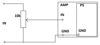
Pin 1 is you signal input. Pin 2 (the wiper) goes to your amp input. Pin 3 goes to your star ground. The pot becomes a voltage divider for the input signal.
Here it is, I guess it is the pretty standard way to do it.
And the input resistors after that are: 1k series and then 47k paralell to GND.
Paralell with the 47k the HF filter cap can be changed but now it is 100pF.
And the input resistors after that are: 1k series and then 47k paralell to GND.
Paralell with the 47k the HF filter cap can be changed but now it is 100pF.
Attachments
Last edited:
Here it is, I guess it is the pretty standard way to do it.
That should work.
News:
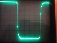
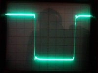
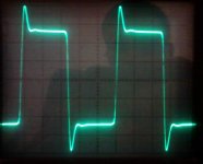
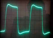
Input: 100(!) kHz square 2Vpp
Output: 2Vpp
1st picture: basic state
2nd picture: ringing eliminated ~95% just with my touch
The amp has 2 PCB: one for the PS, the input and VAS stage
and one just for the OS. At signal level (VAS output -> OS input)
the 2 are connected via a short twisted pair wires.
The 2nd picture shows what is hapening when I touch this wire.
(Both of this pair of waires has a solder in the middle so I can create a galvanic contact with my fingers...)
Does maybe someone have an idea how can I replace myself in this layout with RLC elements..?
Or based on this experiment do you have any idea what the problem can be?
Does my touch change the speed of the amp or just grounds this HF component somehow..?
Attachments

the input likes to see a low source impedance.None of the transistors are conducting I checked it!
Connecting the heatsink directly to the GND / Earth just does not stop the oscillation.
New experiments:
- The oscillation dissapears when I touch the heatsink AND the input wires at the same time.
- If I touch the signal generator's + OUT then the ripple on the square increases...
- The oscillation is the biggest when the input potentiometer is in the middle.
At "0" and at max level there is no oscillation at. The pot is 10k.
I guess this should be something capacitive...?!
The input in this case is the base of the input transistor. All the components before that transistor base have an effect on the source impedance seen by that base.
Including a RF attenuating filter at the input, improves that impedance.
if the last component before the base is the RF filter capacitor then the base
sees that capacitor in parallel to all preceding it.
For testing with sqw, set that cap very small, but for audio you put back the bigger capacitor.
I typically use ~700us as my RF filter. 1k as series resistor and 680pF gives me that and an F-3dB ~200kHz. The base sees the 680pF in parallel to the source impedance plus the 1k. But for testing stability I replace the 680pF with less than 68pF, I used 22pF last week.
I guess thats not the point now, I already tried different values there and the
currently working and ideal value is 100pF. Either bigger or less doesnt help.
I made another try: its enough to touch the VAS output point at the first PCB as well.
It is still a mistery for me what could be here the replacment instead of me...
First of all where does my other end goes to? 2nd: my RLC replacement... 🙂
Add driver and/or output Ccb. Start very small and increase till it stops. Then increase a bit more for safety. Then test with reactive loading.
or increase Cdom (Miller compensation).
Then put back the RF attenuator to it's audio setting.
or increase Cdom (Miller compensation).
Then put back the RF attenuator to it's audio setting.
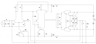
Its basically a symasym but with some mods: 60V triple darlington and 2 pairs of tr-s.
HF comp: input cap: 100pF and at VAS: 100pF nothing else yet.
I dont have the final version with all the changes but I'll draw it soon...
Bye the way I have some improvements: slowing down the VAS helped.
Now I have an overshoot (1st picture) but I dont know why...
I played around the Zobel as well (it was the conventional 10R + 100nF)
and I figured out that 10nF is enough and using 4R7 increases the overshoot
but loading the output with 8R dummy resistive load decreases the overshoot (2nd picture).
What this means..?
Attachments

And a capacitive load increases the overshoot and the ringing a bit,
but touching the VAS output and the output GND at the same time
still helps decreasing the overshoot... 😛
but touching the VAS output and the output GND at the same time
still helps decreasing the overshoot... 😛
Add a Ccb across the other VAS.
I found the real Symasym responds to this.
I also added Ccb to both drivers, 22pF
I also changed the input filter from 2k2+100pF to 300r+2n2F
and I used 4 off 220nF instead of 4 off 100nF HF decoupling
& 4off 1mF + 2off 2m2F instead of 4off 100uF +2off 220uF MF decoupling.
The 10k loading the input can't be right.
Surely it should be >=100k. I use 2M2 here.
The DC coupling leaves the input pair unbalanced.
Have you calculated the VAS bias? I reckon you have ~26mA !
Last edited:
Thanks for the ideas guys!
In order:
I tried the original VAS to GND Cs and Rs but they doesnt change the results as attached.
1st: 100pF + 47k from both VAS output to GND.
2nd: the same with the magic touch... 🙂
(Input: 100 kHz square)
I try the base stoppers next.
Andrew: CCb mod: doesnt help.
Ccb @ drivers: ok I'll try this as well thanks!
10k: it is just there for sim-s as the pot at max level.
I use DC servo instead cap @ FB.
VAS bias: sorry the values are not suerly the final versions I just made a scetch for the layout... 🙂
Attachments
Hmm... Wow... I think I found it... But its very strange to me... :-o
The best result occurs when I connect the VAS output to the heatsink directly with a 2k resistor... 😛
I make some furher testings but at 100kHz it seems like a perfect replacement instead of me and my magic touch...
Please explain why and how this works..! 🙂
The best result occurs when I connect the VAS output to the heatsink directly with a 2k resistor... 😛
I make some furher testings but at 100kHz it seems like a perfect replacement instead of me and my magic touch...
Please explain why and how this works..! 🙂
Hmm... Wow... I think I found it... But its very strange to me... :-o
The best result occurs when I connect the VAS output to the heatsink directly with a 2k resistor... 😛
I make some furher testings but at 100kHz it seems like a perfect replacement instead of me and my magic touch...
Please explain why and how this works..! 🙂
Cancels capacitance of the predrivers?
Hmm... Wow... I think I found it... But its very strange to me... :-o
The best result occurs when I connect the VAS output to the heatsink directly with a 2k resistor... 😛
I make some furher testings but at 100kHz it seems like a perfect replacement instead of me and my magic touch...
Please explain why and how this works..! 🙂
I don't believe, that it's a good solution. It cancel the oscillation, but nobody can predict, that it will be OK, with any load, or even if You build it into a metal box.
Sajti
- Status
- Not open for further replies.
- Home
- Amplifiers
- Solid State
- Heatsink vs OS stability