Oh, please !BTW, these 2 cases are not identical in open loop bandwidth
"...while emitter resistances of the VFA are adjusted in order to get an open loop gain equal to the one of the CFA..."
Take five seconds to verify (or try to understand) instead of arguing with false assumptions.
And all the rest of your comments are about the same. (Both input stage and VAS are in class A).
Last edited:
It is really boring, while you have spend a lot of time with a lot of care to publish a page in order to explain a topology, trying to help people to understand-it, to read comments like the previous one of jxdking.
No, the symmetry of an LTP is not compensating the distortions of the input stage. They are additive. The feedback signal have to pass across the inverting side of the LTP BEFORE to be subtracted to the original signal. Both the distortion and phases shifts of this transistor will modify the feedback signal, making-it less accurate. And we will find its distortions (phase inverted) in the final signal.
The non linear parasitic capacitance of the base junction of this transistor will have an influence on the bandwidth and phase at HF.
Not to mention that we want the two sides of the LTP to be at equal impedance, while we need a high enough input impedance. This lead to a relatively high impedance feedback path in a VFA witch will make a low pass filter with the base parasitic impedance.
In a CFA, we can set the feedback impedance as low as we want, in order to avoid this. And the feedback is working in a common base configuration, witch have always been the preferred at HF.
Reason why a CFA have a better phase margin, and, once both will be compensated for a maximum flat bandwidth, a wider open and closed loop bandwidth, and a better slew rate. It is all about.
CFAs are as old as electronic. (I designed my first commercial amp around 1970, build at thousands of units, very successful at its time, and it was a CFA.)
I don't know why the LTP had became a standard, and this CFA topology neglected until video bandwidths obliged the IC manufacturers to discover again the advantages of this interesting topology.
Both configurations have their advantages and inconveniences, of course. That i tried to enlighten in my article. I believe we have to know them both before to make a choice. As OS did 🙂
And not to be a VFA sectarian for some obscure and non objective reasons: prejudices are never good in audio electronics.
I will not argue more here about this boring CFA/VFA controversy and misunderstandings.
Last edited:
Oh, please !
"...while emitter resistances of the VFA are adjusted in order to get an open loop gain equal to the one of the CFA..."
Take five seconds to verify (or try to understand) instead of arguing with false assumptions.
And all the rest of your comments are about the same. (Both input stage and VAS are in class A).
Open loop bandwidth of both amps are different in your chart you plotted.
OK, I just spent 5 minutes to calculate the open loop bandwidth of them by my own.
Both input stages of them have almost same amount of gm(Transconductance). It is 0.0169A/V in CFA, and it is 0.0170A/V in VFA. I only count for one side (up / down). if combined, the number will be doubled. They are fair enough.
However, look at the miller caps (C6 & C7) in the chart. The one in CFA is 17.6p, and the one in VFA is 28.8p. That's the reason why you will have different open loop bandwidth. Based on my calculation. The unit loop gain frequency in CFA is 6.8MHz, and 4.2MHz in VFA.
When you have miller compensation. the amount feedback you will get does not depend on the OPEN LOOP GAIN any more. The total feedback you will have depends on the outline of 1st-order slope which depends on the OPEN LOOP BANDWIDTH. You don't have to keep OPEN LOOP GAIN equal.
An externally hosted image should be here but it was not working when we last tested it.
Last edited:
... As they are, as explained, the minimal miller values you can set in the both configurations to have the maximum possible flat bandwidth with no peak at HF in closed loop.However, look at the miller caps (C6 & C7) in the chart. The one in CFA is 17.6p, and the one in VFA is 28.8p. That's the reason you will have different open loop bandwidth.
Both amps are equally optimized with the exact same good practice rules.
Sorry that you don't understand this, the reasons of this ... and persist to do not understand !
What do you think ? That i am selling anything, own the CFA patent and cheat to increase some benefits ?
On the contrary, I used a 1K/47 Ohms for the VFA feedback in order to give-it all its chances in bandwidth. Just try with a 10K/470 Okms you would use in a correct and ordinary VFA to balance the base currents of the two sides of the LTP and ...cry !
More than this. As i expected this kind of controversy, i even published a curve with the same miller for the CFA and the VFA:
http://www.esperado.fr/temp/compare_vssa/samemiller-cap.gif
Ok, now ?
That's enough, I think. It is not me who have a flawed mind, as i design -and use- the both topologies and i think I begin to know, after all those years, how to get the best of them both.
Oh, why don't you build and listen to a good CFA, in order to have a real idea of how they behave, instead of trying to demonstrate a supposed superiority of VFAs in all the domains (that, of course, don't exists elsewhere than in the mind of ...Douglas Self ? ;-)
Last edited:
I see your point now. In your case, lower thd is because of more negative feedback in CFA configuration, and which is true. What I was trying to say is that linearity should be open loop behavior, or at least with same amount of feedback.... As they are, as explained, the minimal miller values you can set in the both configurations to have the maximum possible flat bandwidth with no peak at HF in closed loop.
Both amps are equally optimized with the exact same good practice rules.
Sorry that you don't understand this, the reasons of this ... and persist to do not understand !
What do you think ? That i am selling anything, own the CFA patent and cheat to increase some benefits ?
On the contrary, I used a 1K/47 Ohms for the VFA feedback in order to give-it all its chances in bandwidth. Just try with a 10K/470 Okms you would use in a correct and ordinary VFA to balance the base currents of the two sides of the LTP and ...cry !
More than this. As i expected this kind of controversy, i even published a curve with the same miller for the CFA and the VFA:
http://www.esperado.fr/temp/compare_vssa/samemiller-cap.gif
Ok, now ?
That's enough, I think. It is not me who have a flawed mind, as i design -and use- the both topologies and i think I begin to know, after all those years, how to get the best of them both.
Oh, why don't you build and listen to a good CFA, in order to have a real idea of how they behave, instead of trying to demonstrate a supposed superiority of VFAs in all the domains (that, of course, don't exists elsewhere than in the mind of ...Douglas Self ? ;-)
To be honest, your paper is great: http://www.esperado.fr/temp/VSSA/vssa-vs-vfa.html
That paper may be my first time to see how to design a proper CFA. I will definitively try to build CFA some time.
I don't mean to diminish others hard work. Maybe I was too hush to find something to support my original point "LPT configuration is more linear than CFA ones", and ignored some other good things in your paper. Sorry about that. Talking about Douglas Self, I cannot deny that his book play big influence in my design. I remember he did some comparison among different input configuration in open loop scenario. Never mind, I don't want to bring any argument from here.
I do not make money on making amplifier. I have full time job as computer programmer. All basic knowledge I have is from my University in China. Forum is also good place to learn. Maybe my English and technical wording is bad. I always try my best to express what I really mean. I don't mind I am wrong, or someone attack my argument. However I do mind someone categorize me as some kind people and prejudge my personality from that.
I reduced my Rfb values based on this article (section "One remark"):
www.esperado.fr/temp/VSSA/vssa-vs-vfa.html
You will note what Esperado is saying about the resistor values in relation to LTP balance. You may like to revise these in line with his latest comments in post #144. With the capacitor values you have it might make the amplifier slightly more stable.
Last edited:
1- I don't think so. As the open loop and closed loop gains are quite the sames, both have the same amount of feedback. Don't they ?1- I see your point now. In your case, lower thd is because of more negative feedback in CFA configuration, and which is true. What I was trying to say is that linearity should be open loop behavior, or at least with same amount of feedback....
2- However I do mind someone categorize me as some kind people and prejudge my personality from that.
If only the high order distortions were better, we could suspect the phases differences between signal and feedback . . But distortions are (slighly) better in the CFA, even at H2 of 1000 Hz, and i doubt the phase turns of the feedback has an influence at those frequencies. It would be easy to figure out if this is a result of the inverting input stage of the VFA as i pretended. Just need to simulate the VFA in inverting configuration. (Like with OPA, they always behave better in that configuration, because feedback is subtracted in a passive way with no active device in the feedback path).
2- Please, apologize if i was disagreeable, but each time i said a word about CFAs, it is the same kind of battle, and i begin to be a little upset about this VFA dictatorship in the minds of so many people and this strong false idea there is a compensation of distortion due to the +&- input symmetry of the LTP.
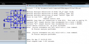
... the example files?
Yes, I had the same errors when I tried to run Esperado's files a while back.
I advised him of the problems but eventually found it easier to fix them myself rather than deal with his reaction.
It would seem they are still not fixed.
I didn't spend much time on it so the results are only tentative but look plausible.
The more accurate (Cordell) models showed that the distortion was worse than claimed.
But only a factor of 2 or so rather than 10 or more, as I initially expected.
The discussion can be found in the Vendor's Bazaar forum, if anyone wants to bother.
Best wishes
David
Last edited:
I am still waiting for your inputs and your promised help. But you did not provided NOTHING else that criticisms in the forum, despite you presented yourself as an expert in LTSpice (that I am not).It would seem they are still not fixed.
Sorry, but after our PM exchanges and your following silence, I ended to believe you are just trolling.
You are still welcome to make-me change my mind.
On my side, i don't care too much: the sims work on my computer and my models organisation, my models are good enough to make the comparison fair and results are close to my IRL measurements, i provided the schematics and some (poor ?) models.
Enough to "fix them" yourself, as you say, so why don't you send-me your perfect files ?
(Of course, i will replace them and credit-you for this)
Last edited:
... despite you presented yourself as an expert in LTSpice...
I do not claim to be an expert in LTSpice, Bob Cordell is far more experienced.
My own, limited research has only confirmed his statement that the NMOS and PMOS models are inaccurate for power FETs, and better replaced with VDMOS models.
So my recommendation was to replace the MOSFET models on your schematic, where it says "PMOS and NMOS", with Bob's "VDMOS" models.
This recommendation is even more emphatic now because there have been some internal improvements to these models by the LTSpice team and Bob tries to keep his models up to date.
Far better to take them directly from him than use my copies.
One recommendation of my own concerns your use of the Tian probe.
There is no "Set" statement in Spice so your "Set" statement will not be effective, if you include a probe then it will not be turned off.
I am sorry that I haven't replied to your last PM.
Best wishes
David
Please, Dave, if you want to help, *send-me* your files, it will be more simple.I am sorry that I haven't replied to your last PM.
There is no link in the interface to update the models or program, how to stay up-to date ?
How to have the most complete list of best available models easily ?
I hate the poor LTSpice interface, all those manipulations we have to do each time we want to change a transient to AC Analysis, and don't understand what the hell they are doing with models. Why don't the developers improve-it ?
Why the Bob Cordels ones are not included in the models provided with the program ?
In case of multiple models, one in the original library, one in the schematic, one in an "include", in witch order are they chosen by the program ?
In this situation, why did the program don't show witch model he gonna use ?
The models of Bob seems to not have been updated since 2010. So what about your: " internal improvements to these models by the LTSpice team".
I don't remember where i found those 2SK1058 & 2SJ162 models and who provided-them to me, but, for sure, i don't invented them. They are not in the Cordell's ones, so, what did i have to do ? replace them with 2SK1056C & 2SJ162C in the schematic ?
As i said, my simulated results were not so far from IRL. IRL was somewhere in the middle of the ones i got with my actual models, and the ones with Bob's ones. So how can-you pretend the superiority of the Bob Cordell's ones in this situation ?
Will it will change the conclusions in this comparison game or just the absolute values of HD, in the same proportions, that i don't care ?
Please, instead of losing time on this, it will help-me if you provide a version of my schematics and a model.txt together, that will work with no contest, for i can replace my files with yours. Is-it too much to ask ?
You have to understand that i used this LTSpice only for those papers, it is years old and i prefer to work IRL with calculations and real measurements for my own work. It was a hard work, and i don't feel spending more days on it, changing all the print screens etc. Don't you understand the problem ?
Last edited:
There is no link in the interface to update the models or program, how to stay up-to date ?
LTSpice checks when the last update occurred and prompts you after a certain time. You can also update manually but I have never bothered.
How to have the most complete list of best available models easily ?
There is no LTSPice Vatican that canonises models and declares them officially blessed. Your best information is probably from the Yahoo user list.
I hate the poor LTSpice interface, all those manipulations we have to do each time we want to change a transient to AC Analysis, and don't understand what the hell they are doing with models. Why don't the developers improve-it ?
I think it's pretty impressive that it works so well and is totally free.
To complain about a free service is not very appreciative.
In case of multiple models, one in the original library, one in the schematic, one in an "include", in witch order are they chosen by the program ?
I don't know, I consider this poor practise and do not do it because of potential confusion.
If you want to know then check it yourself.
The models of Bob seems to not have been updated since 2010. So what about your: " internal improvements to these models by the LTSpice team".
There is thread on DIYaudio about this, with comments by "Keantoken" and Bob. You could find it and learn the latest status there.
Bob also does this work for free, you are lucky to have his comments and models at all.
Will it will change the conclusions in this comparison game or just the absolute values of HD... ?
I don't know
Please, instead of losing time on this, it will help-me if you provide a version of my schematics and a model.txt together, that will work with no contest, for i can replace my files with yours. Is-it too much to ask ?
Probably, yes. You take attempts to help you as personal affronts, so there's not much incentive to spend more effort and money.
I have already made an effort to explain the model problem to you whereas people like Damir, Toni or Paul fix their own problems after only a mention to raise the issue, and they are a bit more appreciative, not just to me but in overall attitude.
You have to understand that i used this LTSpice only for those papers, it is years old and i prefer to work IRL with calculations and real measurements for my own work. It was a hard work, and i don't feel spending more days on it, changing all the print screens etc. Don't you understand the problem ?
Sure, if you don't want to bother then that's fine.
If you do want to improve it then I hope my recommendations help you with models, correct syntax to turn off the Tian probe, and library structure.
Best wishes
David
Last edited:
Of course, happy to share! 🙂
The v1.0 is already finished, stable, and sounds nicely and the v2.0 is just in progress.
The IPS is already up and running (see freshly posted pics @ the symasym thread) and I am working on the OPS now.
Everything is fine so far and since I developed the final cicuit on a prototype, hopefully this will be just an assembly work...
And after that I'll start my journey to the CFA world starting with the "DVSSA" layout.
Or do you have any specific question?
Last edited:
Of course, happy to share! 🙂
The v1.0 is already finished, stable, and sounds nicely and the v2.0 is just in progress.
The IPS is already up and running (see freshly posted pics @ the symasym thread) and I am working on the OPS now.
Everything is fine so far and since I developed the final cicuit on a prototype, hopefully this will be just an assembly work...
And after that I'll start my journey to the CFA world starting with the "DVSSA" layout.
Or do you have any specific question?
With 60 volt supply rails and single output devices, the amplifier is at risk of failure if the output terminals are shorted. I take it you will have some strategy to prevent that from happening.
My question is, how does the circuit look with the latest modifications?
So was my work.To complain about a free service is not very appreciative.
I believe it would had been less time consuming for you(and me) to send-me your files, than to write all those comments.
Anyway, thanks for your advices: i will not make-you lose more time on it. May-be, one of those days, if i am boring myself, with nothing more useful to do, i will update my files, ... when I have understood the proper method.
Last edited:
I dont perpare for shorted terminals, out of scope for me.With 60 volt supply rails and single output devices, the amplifier is at risk of failure if the output terminals are shorted. I take it you will have some strategy to prevent that from happening.
My question is, how does the circuit look with the latest modifications?
Latest schametic: I'll post it as soon as my v2.0 is finished+
In this one I use 3P OPS with NJW0281/NJW0302.
Today I started with the OPS and I cant belive but I have to adjust my HF comp again... 🙄 🙁 😀
I tuned it on the prototype which only differs with a 1P (MJL3281/NJW1302) and has smaller heatsink.
I thought (hoped) the same values will run the final OPS as well but I was wrong... 😱
(OPS is decoupled of course and base stoppers are used as well...)
I dont perpare for shorted terminals, out of scope for me.
Latest schametic: I'll post it as soon as my v2.0 is finished+
In this one I use 3P OPS with NJW0281/NJW0302.
Today I started with the OPS and I cant belive but I have to adjust my HF comp again... 🙄 🙁 😀
I tuned it on the prototype which only differs with a 1P (MJL3281/NJW1302) and has smaller heatsink.
I thought (hoped) the same values will run the final OPS as well but I was wrong... 😱
(OPS is decoupled of course and base stoppers are used as well...)
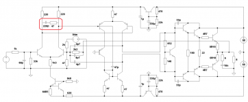
The best waveform of those you posted is that in message #69 i.e. 10kHz sq @25 volts pk-pk into 4R. It appears the circuit for that is largely as shown in #70 without the parts circled in red and some changes in the compensation? - whatever. However there is an anomaly in your sequence of the bias transistor and the stopper resistors. It seems might have had a better basis with which to work than you have now.
Last edited:
This is the latest but I'll post it as soon as all the fine tunings and tests are finished.
Decoupling caps are not on the sch but its exactly like with the SlewMaster OPS.
The new oscillation I mentioned compared to my prototype seems to be solved now with the new red-frame-marked section.
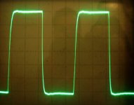
The scope image shows 200kHz without any load yet.
Decoupling caps are not on the sch but its exactly like with the SlewMaster OPS.
The new oscillation I mentioned compared to my prototype seems to be solved now with the new red-frame-marked section.
The scope image shows 200kHz without any load yet.
Attachments
- Status
- Not open for further replies.
- Home
- Amplifiers
- Solid State
- Heatsink vs OS stability