I would put a filtering capacitor, following the 620ohms, to give low impedance point for the CCS input. Maybe it has no any advantage, but will not hurt.
Sajti
Sajti
Ok, thanks!
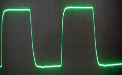
I increased the 330pF @ the top of the LTP with a || 2n2 (47R remained).
Input 10pF removed, Iq still ~ 55mA/device.
Result: 200kHz @ 1V/DIV.
Now only a tiny ripple can be seen on the square wave.
Please help: when is it enough? How do I know whether the phase margin is good now?
What kind of other tests should I make to be 100% sure of stability?
Removing the current limiting resistors can affect the stability as well?
When should I remove them? Or rather a decrease would be better in steps?
Now they are ~160R, but I have values around 20R, 10R, 5R for later...
Attachments
Now only a tiny ripple can be seen on the square wave.
Please help: when is it enough? How do I know whether the phase margin is good now?
What kind of other tests should I make to be 100% sure of stability?
You can't be 100% sure. Try with different sources, and different loads.
Removing the current limiting resistors can affect the stability as well?
When should I remove them? Or rather a decrease would be better in steps?
Now they are ~160R, but I have values around 20R, 10R, 5R for later...
Yes, they can affect. I would reduce step by step, and carefully check the stability.
Sajti
Ok, but with the previous setup I tested it with both resistive (down to ~2R) and
capacitive (up to 22uF) loads but even so it oscillated embarrassingly at a friend... 🙂
So I guess I need some other method as well.
Altough untill now I couldn't remove the input C without having oscillation so this is definietly a good sign, I guess...
And the square wave looks OK or it should be "perfect" without any tiny ripple like that?
Hi Cortez,
Can you please drop me the full schematic - I may come up with some ideas 😉
Cheers,
Valery
Can you please drop me the full schematic - I may come up with some ideas 😉
Cheers,
Valery
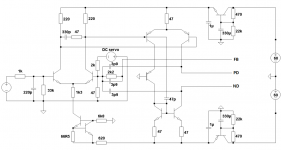
- Input & PS C multplier: BC546B/556B
- CCS: MPSA18
- VAS & Pre & Vbe: 2SA1360/2SC3423
- Driver: 2SA1930/2SC5171
- Power: NJW0281/NJW0302
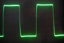
The square wave response perhaps could be improved. I don't like the ringing at all, as they are most likely the sign of instability. Did you design the amp with simulation and what were your expected stability margins? Perhaps it's time to hit simulation again?
I can't tell how much you have to do to get the sufficient stability, but I can show the square wave response of my amp that is rock stable. Here
I can't tell how much you have to do to get the sufficient stability, but I can show the square wave response of my amp that is rock stable. Here
Thanks nattawa that looks very good..!
How did you find out the final C values for the compensation part?
100% simulation or it was just a start?
Sajti told me that these drivers are prone to oscillation > 40V DC PS...
So a series base stopper resistor + few pF C is needed maybe to eliminate this.
How did you find out the final C values for the compensation part?
100% simulation or it was just a start?
Sajti told me that these drivers are prone to oscillation > 40V DC PS...
So a series base stopper resistor + few pF C is needed maybe to eliminate this.
looking at schematic in message 209:
i see bypass caps on the output stage, but none on the input stage.
not the main problem, but also likely should be addressed.
mlloyd1
i see bypass caps on the output stage, but none on the input stage.
not the main problem, but also likely should be addressed.
mlloyd1
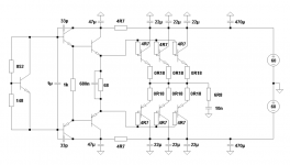
There is a C multiplier for them.
In the meantime I found a very similar problem on a hungarian forum with
these drivers (2SA1930 / 2SC5171) over 40V DC PS (even with EF2 OPS).
They have a very underhand behaviour which often cant be easily detected on the scope etc.
It is prone to oscillation under some mistic circumstances and I guess that caused
my earlier problems with setting the Iq, having oscillation despite my tests, etc.
I'll check what difference it makes if I put an RC (base: 100R + Ccb: 22pF) to them...
Insert 22 ohm base stoppers for triple driver transistors and about 220 - 330pF caps, base to collector. You should also have base stopper resistors for pre-driver bjt-s (about 100 Ohms).
Insert 22 ohm base stoppers for triple driver transistors and about 220 - 330pF caps, base to collector.
Have used this exact arrangement on a 3EF using A1930/C5171 driver transistors. Without these caps had bad oscillation when trying to run any amount of bias (other than zero). With these caps the 3EF behaved itself. The need for this was not shown up in simulations...
Maybe worth a go. They do tend to reduce overall loop stability as the 3EF is slowed down a little. Necessary evil though in some circumstances.
We found same thing with the A1930/C5171, but never had a problem with the good old A1837/C4793. Anyway 22-47ohm base stopper recommended.
Sajti
Sajti
I cant get it: if I put a 82R + 22pF to the drivers I cant set the Iq > 0mA at all with my simple 1k trim + NPN Vbe multiplier... Why..?
There was a time when it went up untill 25mA as I turned the trimm but then it decreased down to 0 in a few seconds...
Other thing: without the 82R but with the 22pF it doesnt oscillate but gives similar result like earlier without the 22pF.
But now if I put in a C at the input LP filter any values from 10pF to 330pF it oscillates immediately... 😱
Waarrhgah.. I think I give it up for today... I am tired... Any comments are welcome! 😱
There was a time when it went up untill 25mA as I turned the trimm but then it decreased down to 0 in a few seconds...
Other thing: without the 82R but with the 22pF it doesnt oscillate but gives similar result like earlier without the 22pF.
But now if I put in a C at the input LP filter any values from 10pF to 330pF it oscillates immediately... 😱
Waarrhgah..
I think I give it up for today... I am tired... Any comments are welcome! 😱Thanks nattawa that looks very good..!
How did you find out the final C values for the compensation part?
100% simulation or it was just a start?
Sajti told me that these drivers are prone to oscillation > 40V DC PS...
So a series base stopper resistor + few pF C is needed maybe to eliminate this.
The compensation capacitor values were among the first to be decided at the beginning of the design. Formulas and details could be found in Bob Cordell's amp design book, a great and easy-reading book, by the way, if you haven't had one. And yes, like many other members, I simulate the design and get an idea how stable the amp will likely be. I've found the simulation worked very well, and I have had no desire to tweak the compensation in that amp since it was built and proven stable.
I have never used 2SA1930/2SC5171 so cannot comment. I have been using MJE15032/MJE15033 for drivers in all my amps.
Generally, compared with 2EF, 3EF OPS needs more care in stability. Damping R-C network is often needed at B-C of pre-driver and/or driver transistors, in addition to base stoppers. I found in the simulation the VAS output impedance at high frequencies can play an important role in taming the instability, too.
I'd find it hard to do without a simulation tool especially when designing an amp that's pushing the stability envelope.
- Status
- Not open for further replies.
- Home
- Amplifiers
- Solid State
- Heatsink vs OS stability