Ok and thanks for your understanding! 🙂
About this Tian method nattawa showed me:
Is this formula and bode plot giving the final loop gain or "just" the open loop gain?
Yes, it shows a loop gain plot in the examples I gave, that is what one needs when examining loop stability.
I played a lot with your versions and then out of curiousity I tried to play with my
original/initial version as well and found that in spice it's not hard to achieve
a stable state I guess but in my case it's not working in the reality, check this out:
Compensation caps:
Results:
On higher output level an overshoot is appearing and increasing with level.
I dont know whether is related to the current limiting resistors?! (22R on both rails)
I dont know where to continue now. Is this due to an OPS issue or just compensation?! 🙁
original/initial version as well and found that in spice it's not hard to achieve
a stable state I guess but in my case it's not working in the reality, check this out:
Compensation caps:
- 3.9pF on FB resistor
- 2x10pF from VAS PD/ND outputs -> FB point
- 822pF from LTP Q2/Collector to current mirrors Base
Results:
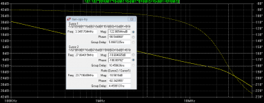
- #1 bode: looks fine in theory... 🙄
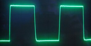
- #2 reality: 200kHz square wave (0.5V/DIV)
On higher output level an overshoot is appearing and increasing with level.
I dont know whether is related to the current limiting resistors?! (22R on both rails)
I dont know where to continue now. Is this due to an OPS issue or just compensation?! 🙁
Attachments

Did you try to:
- Lower the predrivers/drivers quiescent current;
- Add emitter degeneration to LTPs?
- Lower the predrivers/drivers quiescent current;
- Add emitter degeneration to LTPs?
without seeing the schematic you did the simulation with, my guess is that you had multiple compensation loops in that amp, and one of them had a loop gain plot indicating sufficing stability criteria. But that of the rest of them is unknown. You probably need to make sure all loops are stable. It may take a guru to do that, and I sure am not one.
The scope screen shot could be indicating your amp is too slow to respond to a quick signal transition well and was slew over-driven at the square wave edges, in addition to the instability. The wrinkle on the negative-going edge of the square wave could be a sign of slew over-driving condition. At 0.5V/Div that was a really slow transition rate.
The scope screen shot could be indicating your amp is too slow to respond to a quick signal transition well and was slew over-driven at the square wave edges, in addition to the instability. The wrinkle on the negative-going edge of the square wave could be a sign of slew over-driving condition. At 0.5V/Div that was a really slow transition rate.
I simulated the initial schematic - it was very slow with that compensation. I don't know what the current version looks like, but it looks like this is still the case.
First I'd like to test LTSpice and its models without remaking my
amp and solve the stabilisation with as little mod as possible.
Of course if there wont be any other solution I'll start to rebuild it but it's really hard with this finished layout.
(IPS PCB crowded, OPS has the PS section hardwired on the parts side so its not easy... 😱)
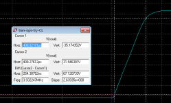
I attach the latest schematic. Both the open loop one with the Tian
bode and the same schematic in closed loop transient analysis.
Slow..? With this setup LT shows me a large signal 264V/us..!
Multiple compensation loops? What does it mean?
It's not enough to check the loop gain with this Tian method?
amp and solve the stabilisation with as little mod as possible.
Of course if there wont be any other solution I'll start to rebuild it but it's really hard with this finished layout.
(IPS PCB crowded, OPS has the PS section hardwired on the parts side so its not easy... 😱)
I attach the latest schematic. Both the open loop one with the Tian
bode and the same schematic in closed loop transient analysis.
Slow..? With this setup LT shows me a large signal 264V/us..!
Multiple compensation loops? What does it mean?
It's not enough to check the loop gain with this Tian method?
Attachments
the compensation caps are placed across stages, forming feedback loops themselves. I don't think these loops can be assumed stable without proof. By the way, the loop gain plot shown in #262 was done with input LPF cap disconnected. In an input stage inclusive compensation that cap sometimes makes big difference.
The DC operation points in the transient.asc schematic in #266 don't look right.
The DC operation points in the transient.asc schematic in #266 don't look right.
What's wrong with the OPs? I checked but found nothing wrong.
I also checked them in reality but they seem to be OK.
I disconnected the OPS and checked the IPS standalone and it looks like as attached.
(200kHz @ 5V/DIV -> I cant drive it further due to the low imp. FB resistors)
It also has some ripple but much better then with OPS but I guess its natural...
Is there a way to test the OPS separately as well? Maybe even without FB..?
Input cap: yes I tried also with and without it but in spice its stable in both case.
With an input cap its moving to an even more stable state but that's all.
So I guess in my case spice isnt covering the reality, right?
Maybe just the models what else could it be..?! 🙄
Attachments
Hi Cortez,
You are looking at one loop with the Tian analysis. How do you know that that the MIC loop made by the 10p caps is stable? How do you know that the loop made by the 822p cap is stable?
We need to work out how to analyze those loops! Otherwise you are working blind.
You only know that the main feedback loop is stable. The more loops you have the more problematic the compensation can be. The more complex it is to get it stable. You just don't know how that input cap affects the other loops.
The closed loop response can sometimes indicate a problem but you can have a situation where an unstable loop is stabilized by another loop.
You are making assumptions ny not having proof as nattawa has pointed out.
Paul
Last edited:
I thought it's enough just to check the main loop but then I was wrong and my sunday went to waste... 
then perhaps it has to do with the initial state of the voltage source at the input if nothing was wrong with the circuit itself......I meant the DC operation points that looked wrong
I thought it's enough just to check the main loop but then I was wrong and my sunday went to waste...
Can you not disconnect the MIC loop / 822p loop and solder some miller caps straight to the legs of the VAS transistors? Even without the LTP degeneration added by nattawa and valery you still have a valid experiment.
Even with large value miller caps it is a worthwhile experiment if you end up with a slow stable amp. Then you know it is worth the time to add the other mods suggested. Stability is number one priority, performance is secondary.
Also, your time spent today was not a waste. It's all part of the learning experience. 🙂
Edit: Maybe try increasing your 33p caps at the pre-drivers. 100 - 150p?
Last edited:
Yeah, I forgot to report about the miller: I tried it with the OPS connected with several values but somehow
the amp didnt "like" it. It was oscilalting and not just with a sinus wave but somehow a more "messy" way.
Now I started to try it without the OPS but likely I wasnt focusing while soldering so the IPS went smoking... 🙁
I guess that's it for today... I'm going to have a rest and continue later...
the amp didnt "like" it. It was oscilalting and not just with a sinus wave but somehow a more "messy" way.
Now I started to try it without the OPS but likely I wasnt focusing while soldering so the IPS went smoking... 🙁
I guess that's it for today... I'm going to have a rest and continue later...
Maybe it's worth reporting exactly what you have tried and the results.
Thing is the topology looks ok. It's getting the details right.
As an aside, since the LTP degeneration was brought up in this thread I have simulated my latest amp with it added and looks promising. So now have similar pain trying to add it into the real thing... Like you have no space.
Thing is the topology looks ok. It's getting the details right.
As an aside, since the LTP degeneration was brought up in this thread I have simulated my latest amp with it added and looks promising. So now have similar pain trying to add it into the real thing... Like you have no space.
...
As an aside, since the LTP degeneration was brought up in this thread I have simulated my latest amp with it added and looks promising. So now have similar pain trying to add it into the real thing... Like you have no space.
an easy solution: cut the trace and put a couple of 1206 or 0805 size SMD resistors on the back side and Voila! 🙂
Yeah, I forgot to report about the miller: I tried it with the OPS connected with several values but somehow
the amp didnt "like" it. It was oscilalting and not just with a sinus wave but somehow a more "messy" way.
Now I started to try it without the OPS but likely I wasnt focusing while soldering so the IPS went smoking... 🙁
I guess that's it for today... I'm going to have a rest and continue later...
The loop gain of an amplifier declines at an initial rate of 6 dB/Octave increasing to 12 dB/Octave towards the upper limit. The greater the decline the greater the changing angle will be.
At some frequency point the phase will reach -180 degrees and if the closed loop gain is one or more it will oscillate. Conventional compensation schemes have a maximum rate of decline of 6 dB/Octave.
Your three 3.9 pF capacitors can be regarded as feedback network from the Vas to the LTP inverting input in parallel with the amplifier output.
In theory from F=1/2pi*R*C. the -3dB point is 6 MHz, however there will be some parasitic Miller capacitance around the Vas transistors.
As long as you persist in your efforts to reproduce square waves of the order of several hundreds of MHz you will have instability problems. Try starting lower on the scale and working your way up - a minus 3dB frequency turnover of 100 kHz perhaps.
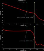
Again - just see what AC analysis shows:
1-st picture - input filter cap is in place (220pF);
2-nd picture - no input filter cap.
This is an oscillator (16.98MHz) by design. Input filter makes the situation a little bit better, softening the magnitude peak and correcting the phase response. But this is a very bad situation - the amp must be unconditionally stable even without the input filter capacitor.
So, the key design mistakes are:
1) Overall OLG is around 160db = way too much; virtually impossible to stabilize.
2) Each stage is prone to local oscillation:
- LTP - no degeneration;
- VAS - no degeneration, huge gain;
- Drivers - too high quiescent current for transistors you use (they like oscillating at high quiescent current).
3) Low impedance NFB network - just adds more issues in this case.
As a result - each stage local issues + huge overall gain + not good compensation approach = screaming oscillator 😉
And again - recommendations:
1) Re-think the quiescent currents;
2) Add emitter degeneration to both LTP and VAS;
3) Increase the NFB impedance.
Your approach at the moment - you create many problems at the same time, trying to fight all of them at once.
Proposed approach - use safe solutions in every stage, having a stable amplifier, and then push it to the limits, if you like, step by step.
Just based on my own experience 🙄
Attachments

Last edited:
Thanks again Valery, you are right, it's just so hard to "let it go" completely
this version as it seemed already so close to the desired final result... 😱
I'm thinking of building a new bench test version where I can easily try all
of your suggestions instead of struggleing with this "compressed" layout
intended for a finished working state and not for debugging and developing...
Thanks again Valery, you are right, it's just so hard to "let it go" completely
this version as it seemed already so close to the desired final result... 😱
I'm thinking of building a new bench test version where I can easily try all
of your suggestions instead of struggleing with this "compressed" layout
intended for a finished working state and not for debugging and developing...
Yep - that would be the right way to proceed 😎
BTW - if that's already the case - do you have any other suggetions?
Should I change some of my BJT types for example?
Smaller ß in the LTP..? Other types for the CCS..?
About LTP quiescent currents: in itself why it is a problem even it'd be ~10mA?
Except the dissipation what other effect/disadvantage it has?
(My goal would be have a high slew rate capability of course with such a high LTP Iq...)
- Status
- Not open for further replies.
- Home
- Amplifiers
- Solid State
- Heatsink vs OS stability