Jason:
I guess U got your sinks afterall. It's about time! where did you get them anyway?
I like your idea of air channel. It reminds me the impulse ventilators in underground car parks. I guess it migth work.
Actually I thought of something similar for PC cooling, without massive heatsinks, of course, only noisy fans and pipes.
Take some temperature readings with and without your gadget to see how good it is(use yourgadget versus fans only)
Member
Joined 2002
yuo solder them to the board first then drill the holes and my c-channel works just awsome ill be fire-in it up when my dam resisters get here for when they do im gunna beat the mail mans *** he is taking for ever.. GRRR..
J'
J'
Member
Joined 2002
i have had them all this time but i was under the impression fromyou that they were to small so i desided to stay UP LATE and design a case to use what i have but ill have to perchase some for my aleph 2 soon as i finnish these..
J'
J'
JasonL
I ordered too a a pair of aleph 5 boards just like yours.( I couldn't resist) what kind of heat are we talking about without any fans? I don't like fans in amps very much... could we be under 60º with your heatsinks?
I ordered too a a pair of aleph 5 boards just like yours.( I couldn't resist) what kind of heat are we talking about without any fans? I don't like fans in amps very much... could we be under 60º with your heatsinks?
Jason, I am concerned that the mechanical connection the Transistors have with your PCB will cause hotspots in the PCB Traces which will increase current flow in the biasing of the transistors. This is called thermal runaway and can be quite hazordous to the FET's. Usually the Heatsink is between the FET's and the PCB to prevent Hot Spotting.
Anthony
Anthony
Hello PedroPO, It is accepted practise not to exceed 55 Deg. C on the surface of a heatsink, that should be your target Max. Temp.
The way human touch perceives heat 60 Deg. C would be to hot to touch. Not good!
Anthony
The way human touch perceives heat 60 Deg. C would be to hot to touch. Not good!
Anthony
Member
Joined 2002
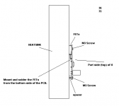
ah hem if i read corectly in the book ( paper ) that was send to me from the guy that designed the board he said to do exactly like how i have it the fets under teh board with the screws so that is what i did..
..
J'
..
J'
Member
Joined 2002
Member
Joined 2002
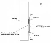
Jason, the physics say that the smaller mass of the PCB will not be able to dissapate the heat radiated off the back of the FET. The heatsink can only absorb heat by convection, the heat from the FET radiates in all directions, while it is true that the large Mass will absorb most of the radiant heat, the PCB is going to HOT SPOT, nice drawings or not.
Of course Jason you are correct, with that design it's the only way to mount output devices. Question is how much heat affects the board itself and maybe few other components (electrolytics for example). I can't comment on this because I didn't try it.
I would mount the FETS on the heat sink and wire the board the the FETs with a short 16 gauge lead wire.
This is how Borberly and Welbourne Labs recommended to mount transistors in desins like that. You have to consider that Mosfet might have 80 deg C or more and it may be too much for PCB.
You don't have to use wires, you can trim the PCB so it doesn't touch devices. OTOH that method must have been check already and nobody seems to complain.
You don't have to use wires, you can trim the PCB so it doesn't touch devices. OTOH that method must have been check already and nobody seems to complain.
Attachments
Member
Joined 2002
i could use that way too...
good description too.. but that means that i will have to cut some of my board so that i dont have to use wires.. or i could put the fets on the sink it self and mount the board inside the case off teh sink..
J'
good description too.. but that means that i will have to cut some of my board so that i dont have to use wires.. or i could put the fets on the sink it self and mount the board inside the case off teh sink..
J'
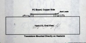
You could mount the FET's to your heatsink form the back side of the board bend the legs 90 Deg and drop the board over the FETS. If you leave enough clearance you couls easily change damaged FET's. You would need to flip FET's around to match GDS on board.
I've seen fets mounted the way JasonL shows. It can be done, wheather it's the best way I dunno (probably not). But I don't see them heating the board up that much. Afterall you're trying to keep them cool, and even though the junction temp between the fet and heatsink will be rather high, they are to-247 devices so the opposite side will be much cooler due to it being insulated.
This seems like a good time to say, I love this Board. Here is the way I mounted the FET's in my 300 Watt Class AB amp.
An externally hosted image should be here but it was not working when we last tested it.
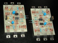
And this is how I mounted FETs on my A75 boards. The trick is to run the traces in a top layer, so there is no problem to solder mosfets.
Coulomb you wouldn't be interested in those boards?😉 Double sided, custom designed, assembled and tested. Same resistors as seen in Mark Levinson equipment.😉
Coulomb you wouldn't be interested in those boards?😉 Double sided, custom designed, assembled and tested. Same resistors as seen in Mark Levinson equipment.😉
Attachments
- Status
- Not open for further replies.
- Home
- Amplifiers
- Pass Labs
- Heatsink question