Member
Joined 2002
Re Hpotter A75 Boards
Missing a few FET's aren't they? Are you sure you do not mean Aelph Boards at 6 FET's each Channel?
Missing a few FET's aren't they? Are you sure you do not mean Aelph Boards at 6 FET's each Channel?
11 mosfets per channel. They are all there. You might say missing trimpots, but they are on the other side.
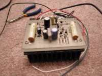
My first A75 used the same board as per original article and the mosfets had small heatsinks ea. However, I noticed that the heat from the amp affected them thermally, so my next two amps featured new boards. The mosfets are mounted directly to the chassis so after an hour all devices have the same temperature and DC drift is stable. The trimpots were accessible through the holes in back plate, so adjusting the amp I didn't have to remove the cover. Very smart idea, because when the cover was removed, the temperature changed and the drift changed.
I picked that from Aleph 0. 😉
Member
Joined 2002
hey potter do you have a pic of your home stereo and all your amps id be realy happy to see them in my email can you do that please im ceriouse to see what amps you have built and what your settup looks like.. i-e speakers amps ect ect all your configureation..
jleaman@citytel.net
J'
jleaman@citytel.net
J'
Some of the stuff you can see here http://www.diyaudio.com/forums/showthread.php?s=&threadid=3233&perpage=15&highlight=A75&pagenumber=1
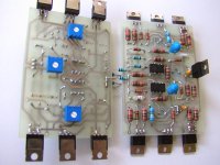
Peter Daniel said:And this is how I mounted FETs on my A75 boards. The trick is to run the traces in a top layer, so there is no problem to solder mosfets.
Coulomb you wouldn't be interested in those boards?😉 Double sided, custom designed, assembled and tested. Same resistors as seen in Mark Levinson equipment.😉
What kinda caps are those blue ones ? and what resistors ? curious.
Peter Daniel said:Trigon, which is one of the members here, bught recently 4 sinks in 11" lengths and paid CAD$360 if I remember correctly. I'd rather prefer to deal with a group of people because then my time would be spend more efficiently. If it's one person what's a difference between ordering them directly from R-Theta or me doing that and sending them to you? As I said before, I cannot cut them nicely and anodize after.😉
How long did it take you to get your heatsinks from R-Theta ? I am going to contact them tomorrow and see what happens.
I really don't care where I get my sinks from I just need to get them 🙂
Peter Daniel said:The caps are tantalum, which I wouldn't use now. The resistors are Dale I'm buying locally.
What do you use when you need small value caps (100pf for example) ? I ordered some Kemets from Mouser, they are rectangular type.
Hi all.
First phone call to R-Theta and guy mentioned that they needed 3-4 days depending on what kind of finish I wanted. Then I have asked for black anodized finish and 11" long, and I went to Mississauga to pick them up as being in close by city. 😉
Other thing Jason, you may as well consider of using this idea on haw to mount your FETs. As most of the heat will dissipate vertically, I mean up, so that board is protected and that’s what I will do with my boards. Take a look at the picture.
One more thing you may consider as a solution. Drill a bigger holes where actual screw head is placed on board so when you tight the FETs the screws are not going to tight the PCB to the FETs only FETs to heatsink and I think that is not bad idea as well.
Hope this helps a little.
Trigon.
😉
Attachments
I know that those boards are so nice that you are very reluctant to do it,😉 but I would just trim them so the mosfets are visible and not covered by the board.
Cdn Heatsinks = $$
Wow, $1,280 cdn. for 16 feet isn't cheap. Lucky for you guys that live in driving distance with this company. I would not like to factor in the shipping costs for them. Note that GST tax is applied for ALL Canadian sales so you're stuck with the 7%. If you buy internationally, there's no GST & PST - but the shipping costs will kill ya.
As for mounting the fets, I don't like the idea of mounting the PCB against the FET. In the previous example I wonder how much force is applied against the PCB where the head of the screw attached to the PCB -> the FET -> Heatsink? In my SoZ amp, the mosfet get VERY hot just by touching the outside case.
Point to point if possible - also when the fet leads are not attached to the PCB - it makes replacing a burnt out fet very fast and easy.
I've got a couple of these heatsinks to use here in the next month.
http://www.geocities.com/super_bq/HiFi/Heatsinks/HS_1.JPG
Member
Joined 2002
Hello JasonL,
There could be two ways of mounting the FETs, like wroted in the Important file that I sent you;
'' Do not use Aluminium L profile for mounting output FET devices.
Mount them on the bottom of the PCB, so that then all together, with the PCB, can be mounted directly on the heatsinks - the output devices should be between the heatsinks and the PCB, like sandwich.
If this is done, be shure that the heatsinks are properly rated for this operation.
Also, for even more efficient cooling, the output devices could be spread over the heatsinks and then connected with the wires to the PCB. The wires should be short as possible ''.
It seems that some peoples who not builted amps that way are little concerned that, if the FETs would be mounted under the PCB, the PCB would run hot.
It is logical that it will, but it will not be same like the FETs.
The most of the heat will be dissipated through metal side of the FETs to the heatsink.
The PCB will be hot over the FETs, but the rest of the PCB will be cooler as you move away from the FETs.
The fiberglass (the PCB is made of it) is not that very good temperature conductive, far less than aluminium.
I used this way in all my amps, and I don't see this as a problem.
It is much better way, than if you would mount the fets with the use of aluminium L-profile - much more hot and PCB and the FETs.
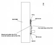
Also, if you are still concerned about this way, you can always leave some small distance between the FETs and the PCB.
Than just increase the size for M3 screw hole on the PCB, so they heads can go through the PCB - directly to the FETs.
This way you will not fasten the PCB to the FETs by screws, it will fly on the FETs leads / legs. (I enclosed the diagram, and I think
that you will understand it)
Also, the most important thing in this project are the heatsinks, and they have most important role in this and other Class A amplifiers.
Regarding the preamp power supply PCBs, I don't have them yet, but they will be available as soon as I find some extra time.
I am also interested in flying airplane models, and they take a lot's of time to build them and sometimes to repair them.
Also, 8 days ago I had a crash ( total one) - I hit the electrical wires of electrical company, and I must say that it was pretty problematic and very disturbing for some peoples.
I guess that I will not fly anymore at the same place, as some peoples almost went crazy.
Best regards,
Kristijan Kljucaric
There could be two ways of mounting the FETs, like wroted in the Important file that I sent you;
'' Do not use Aluminium L profile for mounting output FET devices.
Mount them on the bottom of the PCB, so that then all together, with the PCB, can be mounted directly on the heatsinks - the output devices should be between the heatsinks and the PCB, like sandwich.
If this is done, be shure that the heatsinks are properly rated for this operation.
Also, for even more efficient cooling, the output devices could be spread over the heatsinks and then connected with the wires to the PCB. The wires should be short as possible ''.
It seems that some peoples who not builted amps that way are little concerned that, if the FETs would be mounted under the PCB, the PCB would run hot.
It is logical that it will, but it will not be same like the FETs.
The most of the heat will be dissipated through metal side of the FETs to the heatsink.
The PCB will be hot over the FETs, but the rest of the PCB will be cooler as you move away from the FETs.
The fiberglass (the PCB is made of it) is not that very good temperature conductive, far less than aluminium.
I used this way in all my amps, and I don't see this as a problem.
It is much better way, than if you would mount the fets with the use of aluminium L-profile - much more hot and PCB and the FETs.
Also, if you are still concerned about this way, you can always leave some small distance between the FETs and the PCB.
Than just increase the size for M3 screw hole on the PCB, so they heads can go through the PCB - directly to the FETs.
This way you will not fasten the PCB to the FETs by screws, it will fly on the FETs leads / legs. (I enclosed the diagram, and I think
that you will understand it)
Also, the most important thing in this project are the heatsinks, and they have most important role in this and other Class A amplifiers.
Regarding the preamp power supply PCBs, I don't have them yet, but they will be available as soon as I find some extra time.
I am also interested in flying airplane models, and they take a lot's of time to build them and sometimes to repair them.
Also, 8 days ago I had a crash ( total one) - I hit the electrical wires of electrical company, and I must say that it was pretty problematic and very disturbing for some peoples.
I guess that I will not fly anymore at the same place, as some peoples almost went crazy.
Best regards,
Kristijan Kljucaric
Attachments
real big heatsinks
Hi together,
In all your posted pics i only see small heatsinks, even the pics for future SOZ.
The heatsinks for my future SOZ are bigger than all i`ve seen on Pass sites and other sites in the web.
want to see them?
Regards,
Ralf
Hi together,
In all your posted pics i only see small heatsinks, even the pics for future SOZ.
The heatsinks for my future SOZ are bigger than all i`ve seen on Pass sites and other sites in the web.
want to see them?
Regards,
Ralf
Monster Heatsinks for 50 Watt SOZ
wait until i come to my home-computer.
there i will send the pic to all of you.....
Regards
Ralf
wait until i come to my home-computer.
there i will send the pic to all of you.....
Regards
Ralf
JasonL said:hey potter do you have a pic of your home stereo and all your amps id be realy happy to see them in my email can you do that please im ceriouse to see what amps you have built and what your settup looks like.. i-e speakers amps ect ect all your configureation..
jleaman@citytel.net
J'
I posted some info here http://www.diyaudio.com/forums/showthread.php?s=&postid=47075#post47075
- Status
- Not open for further replies.
- Home
- Amplifiers
- Pass Labs
- Heatsink question