I ordered some cheap toys from Aliexpress.
The idea behind this is to be able to change the voltage on the jfet repeatedly without opening the case.
A 100R multiturn pot to replace P1 and R6 and a digital voltmeters to check the voltage. No idea if it will work, but worth trying 🙂
0.36'' Mini Digital Voltmeter DC 0 100V 3 wire 4 Bit Precision Voltage Meter Panel Tester For Electromobile Motorcycle Car 12V|Voltage Meters| - AliExpress
3590S 2 103L 3590S 100 10K ohm Precision Multiturn Potentiometer 10 Ring Adjustable Resistor + Turns Counting Dial Rotary Knob|multiturn potentiometer|precision multiturn potentiometeradjustable resistor - AliExpress
Any news on how that’s going? …
Difficulties implementing/ does it work as intended?
I need to add a couple of NE5532 buffers after the preamp, as there will be multiple outputs, some with extra potentiometers and most of them with the possibility of a tube amp being connected. Buffers would allow me to add an extra pot without changing the output impedance!
My current schematic:
Input -> H2 → Pot meter → NE5532 buffer → Controlled out
................ ⇲→ Jumper → NE5532 buffer → Pre-out (no volume control)
Anyone with any tips, shoot!
An interesting idea. ... which got me intrigued. Here's a couple of links.
One I found by looking, the other by accident
HTH
a comparison of the better opamps -
Op Amp Shootout – Cycfi Research
and a pretty encouraging blog
from an audiophile blogger who is SERIOUS -
His speakers are LX521s, apparently (someone's comments) driven by power amps from Pass Labs
Never heard of anyone using (apparently) three Pass Labs amps in one pair of speakers
Maybe that’s why he went DIY on the pre 😉
“I was convinced that I could make a preamp based on OPAMPs …
Basically, you are looking at a superb sounding Single Ended preamp that costs less than $150 US dollars. I am using a Burr Brown OPA2134 for the first stage, and an AD8620 for the second stage…
a Jim Hagerman Bugle Power supply and a Twisted Pear Audio Joshua Tree Volume Control
Resonance Frequency
Attachments
Last edited:
From Nelson's PDF:
.
.
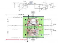
The gain of the circuit (about 9 dB) as presented allows it' to be used as a preamp, and if you provide it with a dual input switch and volume control then you are all set. Alternatively, you can adjust the values of R1 and R2 at the input to set arbitrarily lower gain levels.
I'm using this new H2 as preamp, but I'm wondering where exactly to put the volume pot. At the input I suppose. Could someone show or explain how it should be done, please?.
.
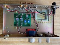
Here's a photo of the previous H2 that I am using as a preamp. Briefly-
RCA L/R in to Alps Pot.
Alps out to H2 IN.
H2 OUT to RCA L/R OUT
I used a small PCB to make my connections to the Alps pot. You can now buy those from the store.
The chassis is an old PA amp that I repurposed.
RCA L/R in to Alps Pot.
Alps out to H2 IN.
H2 OUT to RCA L/R OUT
I used a small PCB to make my connections to the Alps pot. You can now buy those from the store.
The chassis is an old PA amp that I repurposed.
Attachments
From Nelson's PDF:The gain of the circuit (about 9 dB) as presented allows it' to be used as a preamp, and if you provide it with a dual input switch and volume control then you are all set. Alternatively, you can adjust the values of R1 and R2 at the input to set arbitrarily lower gain levels.I'm using this new H2 as preamp, but I'm wondering where exactly to put the volume pot. At the input I suppose. Could someone show or explain how it should be done, please?
.
.
The build guide to the B1 Korg Preamp is a great guide on hooking up the pot, input switch, etc., and would adapt directly to the H2.
This picture from the B1 with Korg Nutube build guide answers the other question I had; What happens to the open end of the pot? It stays unconnected.

.
.
Thanks, I missed that. Wish I could see it in a circuit diagram. That board is obviously double sided.See step #30
Edit: I now see there is a circuit diagram. One has to click on the other pictures to view them.
Not sure this is the correct one, but I'll figure it out later.

.
Last edited:
It had me confused for a moment also, but have a look here:
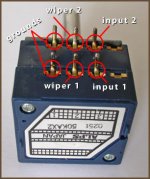
Adding a volume control (pot)to this circuit
This is the normal way to connect a volume control potentiometer.
Adding a volume control (pot)to this circuit
This is the normal way to connect a volume control potentiometer.
I thought this picture was pretty straightforward Skylar88. It obviously simplifies if one removes one set of inputs and the toggle switch. I always have to keep this picture in front of me when wiring up an ALPS pot but the other brands should be the same.
I chose to make my H2V2 as unity gain so it could just be added onto whatever preamp’s signal I chose to modify
I got it from this forum: Wiring up an ALPS RK27 50K Potentiometer
Cheers, Pete
I chose to make my H2V2 as unity gain so it could just be added onto whatever preamp’s signal I chose to modify
I got it from this forum: Wiring up an ALPS RK27 50K Potentiometer
Cheers, Pete
Thanks, I missed that. Wish I could see it in a circuit diagram. That board is obviously double sided.
Edit: I now see there is a circuit diagram. One has to click on the other pictures to view them.
Not sure this is the correct one, but I'll figure it out later.
.
Attachments
Thanks Pete, that helps. I didn't know that the "other" pins should go to ground. It makes sense now. 
.
.
.
.
Skylar88: just remember the “ground” on the pot goes to the return (-) signal on the incoming RCA connections and not to the earth or chassis grounding (prevents any potential ground loops).
Cheers, Pete
Cheers, Pete
Thanks, I missed that. Wish I could see it in a circuit diagram. That board is obviously double sided.
Edit: I now see there is a circuit diagram. One has to click on the other pictures to view them.
Not sure this is the correct one, but I'll figure it out later.
.
Thanks Pete, that helps. I didn't know that the "other" pins should go to ground. It makes sense now.
.
.
Skylar88: just remember the “ground” on the pot goes to the return (-) signal on the incoming RCA connections and not to the earth or chassis grounding (prevents any potential ground loops).
Cheers, Pete
Dang! Why is this so difficult for me to understand? Thanks for pointing that out.
Btw, I welcome the 9dB gain of the H2V2 as preamp for my newly constructed M2 Clone. With the unity gain B1, there is just not enough volume. I deduct from that, that 25W amp power doesn't make up for lack of input voltage from the Sabre DAC - or for whatever reason the volume is too low. The H2 + M2 combination sounds heavenly after I've reduced the H2's T2 voltage to 0.4V higher than the value Nelson wrote on the plastic bag. I have no idea how much 2nd H is left, but it sounds great like that.
The ACA sounded fine with 1% distortion, but with the M2 it is too much. It just shows that not all amps will sound good with the voltage set to the value on the bag.
Last edited:
I've reduced the H2's T2 voltage to 0.4V higher than the value Nelson wrote on the plastic bag.
So, did you increase the voltage or decrease it? 😉
Pete
Dang! Why is this so difficult for me to understand? Thanks for pointing that out.
Just think about it for a moment..we spend the effort to make sure the RCA inputs are isolated from the chassis (by those little plastic sleeves/washers) so one wouldn’t want to defeat that by grounding the pot to the chassis, right?
😉
So, did you increase the voltage or decrease it? 😉
Pete
Sorry about the confusion. The sentence got mangled up while editing it. It should read:
I've reduced the H2's distortion by adjusting T2 voltage to 0.4V higher than the value Nelson wrote on the plastic bag.
Just think about it for a moment..we spend the effort to make sure the RCA inputs are isolated from the chassis (by those little plastic sleeves/washers) so one wouldn’t want to defeat that by grounding the pot to the chassis, right?
😉
True.

- Home
- Amplifiers
- Pass Labs
- H2 V2 BUILD