Unity Gain
I wanted to confirm that for a unity gain, the resistors are as follows for 10:1 ratio R1 = 47K & R2 = 4.7K
Thanks,
Dinesh
I wanted to confirm that for a unity gain, the resistors are as follows for 10:1 ratio R1 = 47K & R2 = 4.7K
Thanks,
Dinesh
Dinesh: see posts 44-51, especially #51
Cheers
Cheers
I wanted to confirm that for a unity gain, the resistors are as follows for 10:1 ratio R1 = 47K & R2 = 4.7K
Thanks,
Dinesh
Thanks for the response. #51 makes it clear.
That's how I built mine..
Cheers
Could a inverting op amp stage be added to restore signal to the correct phase?
Or could two H2 boards be put in series with the second one set up with no distortion.
I'd like to set this up for unity gain with the same phase in and out so I can easily switch it in and out.
Or could two H2 boards be put in series with the second one set up with no distortion.
I'd like to set this up for unity gain with the same phase in and out so I can easily switch it in and out.
Sounds plausible, but maybe the unipolar +12V power supply (from a switchmode wall-wart) could limit your options.
Could a inverting op amp stage be added to restore signal to the correct phase?
Or could two H2 boards be put in series with the second one set up with no distortion.
I'd like to set this up for unity gain with the same phase in and out so I can easily switch it in and out.
That's also the plan I have with mine, put an inverting opamp (like the NE5532) behind it as buffer and also to invert the signal back to original. But just inverting the output wires should do the same i heared. I won't do the build myself as a friend Humbledeer is more specialised in that so for details she will have to answer.
Thanks all, I need to get some stuff off the bench then breadboard up an inverting opamp circuit and test.

NE5532 is internally compensated and should not need any external components besides either biasing, or decoupling. If not running DC biased, you practically don't need anything but the output connected to the inverting input. Just need to perfboard it now, and then wait for later changes to actually design a PCB. A custom PCB will be much easier to use and work around when things get complex regarding feature creep.
Thanks all, I need to get some stuff off the bench then breadboard up an inverting opamp circuit and test.
Why not inverting at source? Some DACs (like mine) have a phase switch and if you have a turntable you can invert connections on cartridge
I would advise against this as this relies on modifying other gear into nonstandard configurations to compensate for your gear that is nonstandard to begin with.

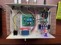
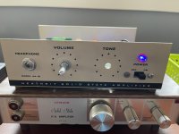
I finished my H2 V2 and put into a small PA amplifier chassis. I added the POZ filter board and kept the on/off switch from the old amp. I added an LED instead of the filament bulb that was there. There's a 50K Alps pot for volume.
I haven't tried it as a headphone amp but the jack is there in the chassis. I'm sure someone will chime in if that's possible.
As always, it sounds great and it's one of the easiest and simplest preamps to build. Thanks, Papa!
I haven't tried it as a headphone amp but the jack is there in the chassis. I'm sure someone will chime in if that's possible.
As always, it sounds great and it's one of the easiest and simplest preamps to build. Thanks, Papa!
Attachments
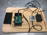
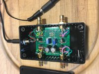
I finished the H2V2 (gift from Nelson! Thank you again), I built it with unity gain as a gift to a very good friend who has an F5 amp and BA 3 preamp he built. Using this he can easily install and uninstall with interconnects.
I used a Triad 12v wall wart with the SMPS filter by Mark Johnson.
Using REW I checked the H2 value at the 10.4 vdc at T2 as written on the bag for the FET's. I measured:
L = 0.60% H2
R = 0.70% H2
With the circuit at unity gain, for 1% H2:
L = 10.08 vdc T2 to ground
R = 10.14 vdc T2 to ground
I used a Triad 12v wall wart with the SMPS filter by Mark Johnson.
Using REW I checked the H2 value at the 10.4 vdc at T2 as written on the bag for the FET's. I measured:
L = 0.60% H2
R = 0.70% H2
With the circuit at unity gain, for 1% H2:
L = 10.08 vdc T2 to ground
R = 10.14 vdc T2 to ground
Attachments
I haven't tried it as a headphone amp but the jack is there in the chassis.
I would be surprised if it drove headphones....
I finished the H2V2 (gift from Nelson! Thank you again), I built it with unity gain as a gift to a very good friend who has an F5 amp and BA 3 preamp he built. Using this he can easily install and uninstall with interconnects.
I used a Triad 12v wall wart with the SMPS filter by Mark Johnson.
Using REW I checked the H2 value at the 10.4 vdc at T2 as written on the bag for the FET's. I measured:
L = 0.60% H2
R = 0.70% H2
With the circuit at unity gain, for 1% H2:
L = 10.08 vdc T2 to ground
R = 10.14 vdc T2 to ground
Very nice, I laid out myself the board and built a test unit using my stash of J113 having IDSS of 24mA perfectly matched. All the remaining part values as published in the article with Nichicon BP series green sleeves as caps for 10uf value. A simple LM317 regulated psu with stable +12vdc.
But using 100R trimmer pots and could not get more than 5.15vdc over the 221R resistor at the T1/2 test points. As Papa suggested need to increase the resistance value or increase the pot. What value trimmers did you use as looking at the pics Bourns W500 does not seem to be a regular value.


Thanks
Last edited:
- Home
- Amplifiers
- Pass Labs
- H2 V2 BUILD