I think, you set a moderate polarizing voltage, a lot of smaller than air-ionization threshold.I did not notice any striking difference between this paint and ordinary acrylic paint
Unfortunately, the polarizing voltage is high, the same as on subwoofers - 5kV.
Since there is a woven mesh as stators on tweeters, they somehow withstand, although the membrane-stator gap on subwoofers is 3 mm, and on tweeters 1 mm. In this way, I increase the sensitivity at high frequency.
One thought haunted me - high frequencies like a hard surface, not a soft one, and I decided to go for another experiment - instead of a 6 micron film, put 15 microns. It worked, the high frequencies became more distinct and there were simply more of them.
While I listen, the verdict will be later.
Hi,
5kV (measured where?) for a 1mm d/s spacing means that there is serious loss of voltage somewhere, typically within the stator insulation layer, but here probabely in form of leakage.
Maybe not enough isolation towards the wooden frame?
A simple blinker circuit (a small neon-bulb w. typically 94V of ignition voltage and a paralleled cap of ~100nF connected in series to the bias supply) would show if there were leakage issues.
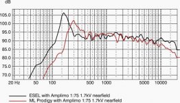
Diaphragms with thickness >6µm lead to a drop in HF SPL due to mass related effects ... see the comparative measurement of my ESEL Panel vers. a ML Prodigy panel, hence 3.5µm vers. 12µm of diahragm thickness.
The Prodigy is dropping in HF response from >7kHz, reaching -6dB@17kHz.
jauu
Calvin
5kV (measured where?) for a 1mm d/s spacing means that there is serious loss of voltage somewhere, typically within the stator insulation layer, but here probabely in form of leakage.
Maybe not enough isolation towards the wooden frame?
A simple blinker circuit (a small neon-bulb w. typically 94V of ignition voltage and a paralleled cap of ~100nF connected in series to the bias supply) would show if there were leakage issues.
Diaphragms with thickness >6µm lead to a drop in HF SPL due to mass related effects ... see the comparative measurement of my ESEL Panel vers. a ML Prodigy panel, hence 3.5µm vers. 12µm of diahragm thickness.
The Prodigy is dropping in HF response from >7kHz, reaching -6dB@17kHz.
jauu
Calvin
Attachments

I took a ready-made voltage multiplier circuit mathematically calculated for 6 kV, but I do not connect to the edge of the multiplier, but a little earlier. Although I have something to measure.Hi,
5kV (measured where?) for a 1mm d/s spacing means that there is serious loss of voltage somewhere, typically within the stator insulation layer, but here probabely in form of leakage.
Maybe not enough isolation towards the wooden frame?
A simple blinker circuit (a small neon-bulb w. typically 94V of ignition voltage and a paralleled cap of ~100nF connected in series to the bias supply) would show if there were leakage issues.
Diaphragms with thickness >6µm lead to a drop in HF SPL due to mass related effects ... see the comparative measurement of my ESEL Panel vers. a ML Prodigy panel, hence 3.5µm vers. 12µm of diahragm thickness.
The Prodigy is dropping in HF response from >7kHz, reaching -6dB@17kHz.
jauu
Calvin
As for the tweeter, I previously connected it to its polarization operating voltage, since the stator was NOT previously painted, then I applied 1kV to it (according to air insulation 1mm.-1kV.), Then 2, and then I think, well, I’ll connect it to all the voltage that I had on the bass multiplier, the tweeter worked several times louder and there were no visible defects, I left it like that 🙂.
Leaks on the wooden case ... I have a special insulator design, it completely covers the end of the stator, there should be no leakage, especially since it is made of PVC material. The wooden case is dry and varnished.
Although everything can be in our life, including leakage.
Purely subjectively, I think that a tightly stretched membrane, small in width, will be rigid and high frequencies will be better repelled from it than from a large and, accordingly, sagging one.
Well, a thin membrane, by definition, cannot be solid, even when it is strongly stretched, again, it cannot be strongly stretched, otherwise it will burst.
But yes, the reverse side of the matter is the mass, so you have to choose.
The 6 micron membrane worked for me even with a rise to 20 kHz, I will take measurements at 15 micron, see what it shows.
Hi,
applying bias leads to an mechanical offset of the diaphragm.
Stretching the diaphragm very tight reduces the amount of offset.
As the stretching force is almost orientated perpendicular to the offsetting electrical force it must be very strong to keep the offset small.
If the free vibrating area spans more than a certain critical range, even the hardest stretching may not be sufficient to keep the membrane from collapsing into one of the stators.
As a rule of thumb ... reducing the free vibrating membrane area to below a relationship of 1:70 -1:100 against the membrane vers. stator distance (d/s) allows for high enough stretching force values to keep the membrane off of the stator under all circumstances.
Also a higher mechanical tension allows for higher Bias voltages, hence higher efficiency/higher SPL.
This at the same leads to a more dynamic, lively sound reproduction of the panel.
With 1mm d/s a membrane strip could be as wide as 70-100mm, thereby utilizing membrane area versus d/s most efficient.
Both my large 40x160cm panel as well as the smaller 25x125cm panel (and ML working with very similar sets of parameters) feature 1mm d/s and can be used from ~180Hz resp. ~250Hz with full dynamic range.
With a 20mm wide strip the d/s could be reduced to 0.5mm if one could manufacture such a long strip with that level of mechanical precision.
That would allow for lower Bias voltage to achieve the same fied strength in the ´airgap´ ... it increased the capacitance of the panel, allowing for lower transformation factors of the audio trannie, thereby increasing bandwidth, reducing risk of arcing and reducing ageing of components and materials.
Admittedly though it might become difficult to find a mating partner that can keep up with the dynamic range of such a panel.
In that case it might be an advantage to not chase for highest efficiency but to ease the requirement for precision mechanics.
The ML Sequel for example wasted about 12dB in the equalizing and xover circuitry to linearize the panel´s amplitude response and to match the SPL levels of bass driver and panel.
That this ´panel rapeing´ didn´t end in a sonic disaster only proved how superior a ELS plays against dynamic mid- and high frequency drivers.
Driven by an high quality transformer via an active xover the Sequel panel could not only play much louder, but also far better sonically.
As you can see in the diagram I attached earlier, the thinner membrane shows less sag in amplitude response at the upper end.
At the lower end one can see that the higher stretching force of the thicker membrane of the ML Prodigy panel leads to a higher base resonance (about 170Hz vers. 250Hz).
Both membranes elongate by ~1.5-2% in length under these stretching forces, which is a sensible limit for these thin membranes.
And while the thicker membrane can be stretched harder this doesn´t mean that the thin membrane can only take small stretching forces.
Even the 3.5µm membrane was able to crack a massive wooden stretching frame made from 40x50mm beech wood.
Besides the lower mass related amplitude sag at the upper end the thinner membranes present even more small acoustic details.
It´s not without reason that Stax´s top of the line ear speakers utilize a 0.9µm thick membrane.
jauu
Calvin
Yes, you are right, thanks for the information, extended information.
But the fact is that in my tweeter there is no question of going down in frequency too low, because the "subwoofers" work up to 1000 Hz.
The very quality of high frequencies is important to me, that is, not just their presence under the measurement of a microphone, but also the acoustic presentation and perception of them by the human ear.
What I've been doing lately is trying to find the best quality for my individual perception, in this case high frequencies.
I can say with confidence that the previously tested constructions of drivers of different physical shapes did not give such high quality and accurate reproduction of precisely high frequencies.
And this is a narrow strip of the driver itself and a well-stretched film, which contributes to a good repulsion of high frequencies from the surface of the film.
This is my already established conviction as a result of experiments, as I already wrote, on many options. Maybe they (options) were not too perfect, but they are mine and heard by my ear 🙂
The only drawback of such a construction of the tweeter is insufficient sensitivity, due to the small radiation area, therefore, one has to go to extreme conditions, such as increased polarizing voltage, which does not correspond to the membrane-stator gap, but it works and gives a result.
It´s not without reason that Stax´s top of the line ear speakers utilize a 0.9µm thick membrane.
Headphones are a separate issue, in which top-end Stax 007 or 009 or 9000?
Firstly, 007 has a small membrane area, I disassembled this model, they were damaged, there is a double membrane at a very close distance from each other, but it is about 1 micron thick.
They therefore have a very characteristic frequency response with a peak at 80 Hz and a downward slope, because the double membrane increases its own resonance.
At 009, it’s generally interesting there, they have a variable thickness of the membranes, thin in the middle, and 2 microns towards the edges.
Hello friends.
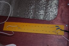
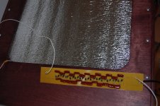
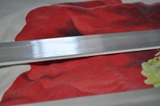
I decided to cover with white paint, and then varnish the stators for the high-frequency emitter.
I made completely new stators and painted them separately from the insulators.
Before that, I also painted the old stators, but the insulators were glued and had to be painted with them, it didn’t work out very well, but I tried it on the sound, the polarizing voltage was almost halved, and the return turned out a little more.
So after such an experiment, I decided to do everything as it should.
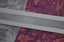
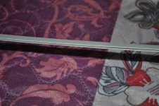
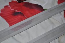
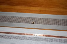
I am attaching a few photos of the stators themselves with insulators and the insulator itself is made of white and soft PVC, it has very good insulating properties. The same insulators are only several times thicker on my subwoofers.
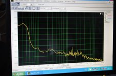
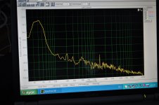
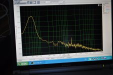
I am also attaching photos of 30Hz, 40 and 50 signals taken with a microphone from a distance of 2.8 meters from the sound source.
The small peak at 1.5kHz is the laptop fan noise.
I decided to cover with white paint, and then varnish the stators for the high-frequency emitter.
I made completely new stators and painted them separately from the insulators.
Before that, I also painted the old stators, but the insulators were glued and had to be painted with them, it didn’t work out very well, but I tried it on the sound, the polarizing voltage was almost halved, and the return turned out a little more.
So after such an experiment, I decided to do everything as it should.
I am attaching a few photos of the stators themselves with insulators and the insulator itself is made of white and soft PVC, it has very good insulating properties. The same insulators are only several times thicker on my subwoofers.
I am also attaching photos of 30Hz, 40 and 50 signals taken with a microphone from a distance of 2.8 meters from the sound source.
The small peak at 1.5kHz is the laptop fan noise.
Attachments
Hi friends.
I have some news.
Earlier I wrote that I lacked the sensitivity of the tweeter drivers, but the reason turned out to be trivial.
The thing is that I was feeding them the bias from the bass driver multiplier and it didn't come full.
Subsequently, I decided to quickly make separate voltage multipliers for the tweeter drivers, did a simple but reliable variant - hinged mounting.
The sensitivity has increased more than twice.If before I turned the volume knob on the amplifier for the HF drivers for 3 hours to equalize the volume of the two bands of speakers, now enough to 12 hours, and this is a very big difference in volume.
That's why I had a problem with voltage breakdown in the HF drivers, because I had to apply a very high voltage to the stators from the amplifier and transformers.
I decided to do everything in a new way - stators, isolators and diaphragms, I went back to 6 micron diaphragms, they are really better than 15 microns, the sound is much more refined.
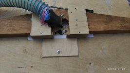
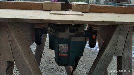
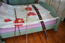
I am posting photos of what I did insulators, or rather milled 1mm deepening for the grid stators, brought insulators from the garage and put on the most expensive and softest place, the bed, while my wife was at work))).
I also made an acoustic registration for the bass drivers, it is very unusual and goes against all the rules of such a registration, but it works great with electrostatics. But it is still in rough draft, it is necessary to do everything clean and then I will show it to you.
I have some news.
Earlier I wrote that I lacked the sensitivity of the tweeter drivers, but the reason turned out to be trivial.
The thing is that I was feeding them the bias from the bass driver multiplier and it didn't come full.
Subsequently, I decided to quickly make separate voltage multipliers for the tweeter drivers, did a simple but reliable variant - hinged mounting.
The sensitivity has increased more than twice.If before I turned the volume knob on the amplifier for the HF drivers for 3 hours to equalize the volume of the two bands of speakers, now enough to 12 hours, and this is a very big difference in volume.
That's why I had a problem with voltage breakdown in the HF drivers, because I had to apply a very high voltage to the stators from the amplifier and transformers.
I decided to do everything in a new way - stators, isolators and diaphragms, I went back to 6 micron diaphragms, they are really better than 15 microns, the sound is much more refined.
I am posting photos of what I did insulators, or rather milled 1mm deepening for the grid stators, brought insulators from the garage and put on the most expensive and softest place, the bed, while my wife was at work))).
I also made an acoustic registration for the bass drivers, it is very unusual and goes against all the rules of such a registration, but it works great with electrostatics. But it is still in rough draft, it is necessary to do everything clean and then I will show it to you.
Attachments
-
 DSC_0062.JPG487.1 KB · Views: 187
 -
 DSC_0061.JPG501 KB · Views: 173
 -
 DSC_0064.JPG396.7 KB · Views: 175
 -
 IMG_20220908_153200.jpg405.5 KB · Views: 176
 -
 IMG_20220908_151004_1.jpg443.5 KB · Views: 176
 -
 IMG_20220908_150955_1.jpg757 KB · Views: 221
 -
 IMG_20220908_154221_1.jpg611 KB · Views: 195
 -
 DSC_1253.JPG338.9 KB · Views: 178
 -
 DSC_1255.JPG342.4 KB · Views: 172
 -
 DSC_1260.JPG242.3 KB · Views: 187
Beautiful work!Ten years ago I built giants like this))):
All the same, the high-frequency radiator does not give me peace of mind, I had to redo it once again.
The thing is that sometimes I like to listen to music at a fairly high volume and breakdowns happen on the stators.
The gap is 1 mm membrane-stator, stators painted white paint and five layers of varnish, but it does not help protect against breakdown voltage signal from step-up transformers (Ktr.1-100).
In general, I made new stators and insulators, insulators made 2mm thick, stators are not covered with paint and varnish.
By the way, it seemed to me that the unpainted bronze stators sound better than painted (subjective).
As a result I raised the polarizing voltage and the sensitivity remained the same, but with more confidence that there will be no breakdown.
Tested the new drivers at higher power, they behave perfectly.
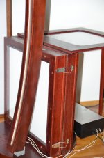
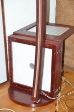
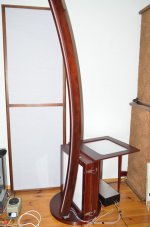
I rethought the positioning of the drivers, now they stand on the floor and lean against the subwoofers.
In the photo the old and new insulators.
The thing is that sometimes I like to listen to music at a fairly high volume and breakdowns happen on the stators.
The gap is 1 mm membrane-stator, stators painted white paint and five layers of varnish, but it does not help protect against breakdown voltage signal from step-up transformers (Ktr.1-100).
In general, I made new stators and insulators, insulators made 2mm thick, stators are not covered with paint and varnish.
By the way, it seemed to me that the unpainted bronze stators sound better than painted (subjective).
As a result I raised the polarizing voltage and the sensitivity remained the same, but with more confidence that there will be no breakdown.
Tested the new drivers at higher power, they behave perfectly.
I rethought the positioning of the drivers, now they stand on the floor and lean against the subwoofers.
In the photo the old and new insulators.
Attachments
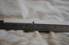
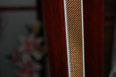
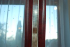
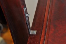
Further. The bass segment stators are made of 3mm metal. thick for increased rigidity. The working size of the bass panel is 500 / 500mm. The high-frequency strip is made with a height of 1900mm. and a width of 20mm. Here I must step back a little and tell you why I came to such a construction of a high-frequency emitter. Once visiting this forum, I posted a photo of my ESL where horizontally bent panels a la Martin Logan appeared and I was criticized by several people for this that allegedly these panels emit an incorrect high-frequency signal and at the same time the temporal characteristics are violated, that is, an interference porridge is obtained. I thought a lot))), asked about the size of the emitter and the long waveform, as well as the stereo format. As a result, I came to the conclusion that in the horizontal area the high-frequency emitter should not exceed 20mm in physical dimensions. In this case, we will have a wide-beam signal up to 16000 Hz, since the wavelength is 20mm. will correspond to 16000Hz. In the photo I am laying out a rough version of the articulation of two strips, then I will make a special mount with the ability to adjust the high-frequency emitter in the vertical plane, but for now everything is kept on scotch tape))). Further. The high-frequency radiator is bent in the vertical plane in order to collect the signal from the entire length of the radiator (1900 mm) into one point at the listener's ear. The bending radius in the vertical plane is 3000mm, this is the distance I have from the speakers to the sofa with my beloved))) As a result, the sound is very accurate and the sensitivity is approximately doubled. The high-frequency emitter stators are made of a woven mesh material of bronze and high acoustic transparency. The working range of these emitters is 600Hz-ultrasound.
> The high-frequency strip is made with a height of 1900mm. and a width of 20mm.
Nice design! So If I understand correctly this strip is closed on the back, or is it open?
Any idea if your design could be extend in LF below 600Hz (200Hz would be nice)?
What causes the 600Hz limitation in your design?
Hi.Nice design! So If I understand correctly this strip is closed on the back, or is it open?
Any idea if your design could be extend in LF below 600Hz (200Hz would be nice)?
What causes the 600Hz limitation in your design?
I wrote here earlier that I wanted to make a good quality tweeter.
And the quality depends on purely acoustic problems.
A big and flat transducer or a curved one like the ML cannot reproduce high frequencies correctly because of the acoustic capabilities.
That's why I chose the size 20mm (sound wave length at 16kHz),and now even less -17mm.
There is no point in extending downward the frequency range of such a transducer, because in the lower range the electrostatic also plays, its range is 25-1000Hz.
I think I went crazy, yesterday I made it with 2 micron film, the sound dissolved into space, I heard a lot more details in terms of timbre play.
Attachments
Nice!Hi.
I wrote here earlier that I wanted to make a good quality tweeter.
And the quality depends on purely acoustic problems.
A big and flat transducer or a curved one like the ML cannot reproduce high frequencies correctly because of the acoustic capabilities.
That's why I chose the size 20mm (sound wave length at 16kHz),and now even less -17mm.
There is no point in extending downward the frequency range of such a transducer, because in the lower range the electrostatic also plays, its range is 25-1000Hz.
I think I went crazy, yesterday I made it with 2 micron film, the sound dissolved into space, I heard a lot more details in terms of timbre play.
From the picture I can see it's open baffle.
So your baffle width is ~6cm which is probably the beggest reason your design tweeter does not go lower than 600Hz.
I agree you don't need it, but I was thinking about combining with conventional subs that x-over at 200Hz or so..
There is a nuance, ideally for me this HF should be open, but he formed a hump in the frequency response at 500 Hz, a little unpleasant hump that I had to remove the equalizer, but I made a mistake in the manufacture of insulators from white PVC and the resulting width of the driver was 17 mm, and this in turn took away this hump))).Nice!
From the picture I can see it's open baffle.
So your baffle width is ~6cm which is probably the beggest reason your design tweeter does not go lower than 600Hz.
I agree you don't need it, but I was thinking about combining with conventional subs that x-over at 200Hz or so..
The open radiator is better already that the sensitivity of the driver is higher.
This tweeter can not reproduce lower frequencies because its area is small and accordingly the piston mode is very limited,but it is all in the plus for high frequencies.
Again, previously I thought that the work of the electrostatic in the high frequencies is not sufficiently disclosed in large drivers because of the acoustic problem.
Making a narrow driver confirmed this problem, the fault is not the electrostatic, but its shape.
Hi.
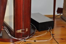
Finished completely with my speaker system.
Made a box for the transformers and multipliers.
All the wires are inside and soldered straight solder, I did not want to put connectors, I thought that it is enough connectors on the amplifiers and speaker systems.
At the moment I use two amplifiers, for the bass range amplifier class "D" on battery-powered 36 V, and for the high-frequency driver, a Chinese high end class amplifier "Tonewin".
I also use the equalizer as a clipping filter for the tweeter driver, cutting off everything below 500Hz.
Also as a preamplifier I use a tube Dier amplifier.
As sources of sound and music are digital and analog sources, about them I will write more later.
Attachments
- Home
- Loudspeakers
- Planars & Exotics
- Full-range, two-way ESL