Unfortunately, my skills are not enough to carry out such a project(the special amplifier)🙂 The application of traditional step up transformers remains. How sensitive is it? Maybe there would be photos of the assembly?
You mean step-up transformers?Unfortunately, my skills are not enough to carry out such a project(the special amplifier)🙂 The application of traditional step up transformers remains. How sensitive is it? Maybe there would be photos of the assembly?
They are sold in Australia by an electrostatics company.
I bought a transformer for a high-frequency panel from them, I liked the high frequencies, but my panel is very small area, so the capacitive load will be small, and therefore the highest frequencies will not be cut off.
They also have bass transformers.
But their requirements are a little less and I ordered here at my firm specializing in toroids, gave them the technical specifications and they wound toroids, they turned out very successful.
But transformers should not be considered the best option.
A step-up transformer is like a lever of a stick, you have 1 meter on your side and 200 meters on the other side and you are trying to control the stick🙂.

But transformers should not be considered the best option.
Roger Modjeski RIP said the same and like you he loved ESL's. He was the expert on DD-ESL's and gave some entertaining background on Direct Drive history here;He claimed 5kv x 0.5A peaks from his reliable design. Imagine what that could do for your system.
Thank you.
Have you tried cascade assembly to lower the resonance, like in David Lucas ESL? Is it effective?
https://www.diyaudio.com/community/threads/shock-wave-electrostatic-subwoofer.233059/#post-6230181
Have you tried cascade assembly to lower the resonance, like in David Lucas ESL? Is it effective?
https://www.diyaudio.com/community/threads/shock-wave-electrostatic-subwoofer.233059/#post-6230181
No, I'm not familiar with this particular authorship of the ESL idea.Thank you.
Have you tried cascade assembly to lower the resonance, like in David Lucas ESL? Is it effective?
https://www.diyaudio.com/community/threads/shock-wave-electrostatic-subwoofer.233059/#post-6230181
But sometime in 2013 I was talking to a man from Siberia on Skype and he talked about this idea.
My personal, dilettantish opinion is that an electrostatic can not work in such a design as a bass segment.
We all know well that the electrostatic has a very weak motor against the electromagnet.
The electrostatic does not have enough force to push large masses of air out of this "labyrinth".
What is the point of such a design as I have, to combine 6 membranes and make them work for pressure, not volume.
Namely, the lack of energy of a weak electrostatic motor is compensated by isobaric membrane operation, when the membranes push each other in the *** while gaining energy in the last membrane (the sixth) to push the necessary mass of air into space.
There is no such thing in the EMT design.
Very good idea, This is how you can turn weakness into strength. It reassured me that this was the right direction.
No question in my mind that the best sound I ever achieved was with a direct drive amp powering Dayton-Wright speakers. Pretty close to Sanders concept but amp essentially was powering a bank of resistors since ESLs don't need power (only voltage). Tube B+ was 2300 v and XO at 130 Hz to a Klipschorn bass. Worked great for 20 years. Very dangerous.
Friends, on the eve of the New Year I made a record of good old jazz.
After all, the Australian transformers rocked my high-frequency satellites well:
https://drive.google.com/file/d/1pPBxZC4s_C4LGxKR3A7Xn6yoInTQawde/view?usp=sharing
After all, the Australian transformers rocked my high-frequency satellites well:
https://drive.google.com/file/d/1pPBxZC4s_C4LGxKR3A7Xn6yoInTQawde/view?usp=sharing
I read a little bit about these Canadian ESL , very interesting option.No question in my mind that the best sound I ever achieved was with a direct drive amp powering Dayton-Wright speakers. Pretty close to Sanders concept but amp essentially was powering a bank of resistors since ESLs don't need power (only voltage). Tube B+ was 2300 v and XO at 130 Hz to a Klipschorn bass. Worked great for 20 years. Very dangerous.
Friends, some trombone, saxophone and female vocals on my ESL recordings.
https://drive.google.com/file/d/1jzyKgShHCl4Cz_dYu4xIVynNpCgc4NVl/view?usp=sharing
https://drive.google.com/file/d/1jzyKgShHCl4Cz_dYu4xIVynNpCgc4NVl/view?usp=sharing
Sounds great. Happy days.some trombone, saxophone and female vocals on my ESL recordings.

Happy New Year!!!Happy New Year.🙂 Very fine jazz records.The sounds great are in my opinion too.
Starting to think about how to make a box for two transformers and a polarizing voltage multiplier for the membranes.
It will be some kind of flat box about the size of a subwoofer and will stand behind the subwoofer.
By the way, all the wires, literally all that connect all the components, which are transformers, multiplier, wires leading from the amplifier to the transformers and from transformers to the speakers, I used silver-plated and in fluoroplastic insulation even Soviet production.
But to do this I had to go to a nearby town and find an elderly man who has kept these wires, I remembered how 15 years ago I saw him selling them at the radio market and I accidentally saved his phone.
And all the wires that are inside the subwoofers (there are a lot of wires leading to the stators and diaphragms), I used too of this type, but in double insulation.
Connectors also used Soviet, I accidentally found them at the radio market, these connectors instrumental type material of white bronze.
I decided that since I'm making it for myself, I don't need to put beautiful Chinese "gold" connectors here😆.
Attachments
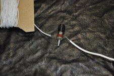
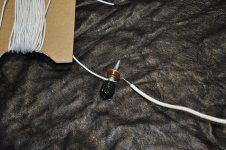
They are brand new and unused.
The soldering is done at the end.
I just came across them at a radio market and I couldn't stand it.
These connectors were used in laboratory instruments about 50 years ago.
But I don't have any complaints about the connectors. The only thing I think: the less mass of metal in any connector, the less coloring in the sound will be.
Ideally, it is to twist two wires with the largest area, but here it will be the only connector on the signal path from the amplifier-transformer-speaker.
We must remember that in electrostatics, where there is high voltage, the most important thing is good contacts 🙂 .
I made measurements of the capacitance of the high and low frequency panels.
The high-frequency one is 226 picofarads,
and the low-frequency panel is 1850 picofarads!
Logically two band amplifiers are required.
Last edited:
- Home
- Loudspeakers
- Planars & Exotics
- Full-range, two-way ESL