Hello.
Of course, the integration of two strips of electrostatics is almost seamless, because I have two planar emitters.
If in the low-frequency register there was a speaker with a magnet, a coil and a cone-shaped diffuser, then integration even in this sense would be difficult due to too different physical forms of the radiator.
Further, in this case, I do not use electronic filters at all that rotate the phase, I get by with the frequency characteristics of step-up transformers in the lower register, they work up to 1000 Hz., And then there is a gentle decline.
A high-frequency transducer physically cannot operate below 600 Hz, since in such a narrow transducer (20 mm) the piston mode is almost completely absent. Or rather, it is negligible.
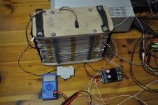
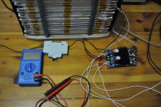
By the way, now I use two different amplifiers, that is, channel-by-channel amplification, in the low-frequency register I use an amplifier in class "D".
And I feed it from the battery (30 volts).
The battery is capacious 48Ah.
It will be enough for 1 month of everyday listening for at least 6 hours a day, and I greatly underestimated this.
To be honest, I'm delighted with this baby that fits on a child's palm 🙂.
He does not care at all for such a complex load as electrostatic subwoofers.
The temperature on the microcircuit heatsink does not exceed 50 degrees Celsius. The real power is 125 watts per channel, the advertising power is 350 watts per channel 🙂.
Attachments
Hi,
"And we remember well that the sound wave length of 20 mm is 16 kHz. That is, in this case, the range up to 16 kHz will NOT have sound directionality, but is broadly directed up to 16 kHz."
You charmingly miss to mention the acoustic phase cancellation.
Such a thin strip requires a lot of equalizing towards the lower bandwidth limit.
A 25cm wide panel suffers from phase cancellation from below 800Hz already.
"Of course, the integration of two strips of electrostatics is almost seamless, because I have two planar emitters.
If in the low-frequency register there was a speaker with a magnet, a coil and a cone-shaped diffuser, then integration even in this sense would be difficult due to too different physical forms of the radiator."
Seamless integration happens when distribution character and xover characteristics of the two branches match.
The branches don't need to be of same type, like two planars or two dynamic drivers.
The different shape of the two planars give You the same integration problems as if You used a coned dynamic driver of same dimensions.
Distribution character doesn't care about wether the motor is of magnetic or electroststic nature.
jauu
Calvin
Ok, then please answer, is the acoustic phase suppressed by a thin but long organ pipe?Hi,
"And we remember well that the sound wave length of 20 mm is 16 kHz. That is, in this case, the range up to 16 kHz will NOT have sound directionality, but is broadly directed up to 16 kHz."
You charmingly miss to mention the acoustic phase cancellation.
Such a thin strip requires a lot of equalizing towards the lower bandwidth limit.
A 25cm wide panel suffers from phase cancellation from below 800Hz already.
"Of course, the integration of two strips of electrostatics is almost seamless, because I have two planar emitters.
If in the low-frequency register there was a speaker with a magnet, a coil and a cone-shaped diffuser, then integration even in this sense would be difficult due to too different physical forms of the radiator."
Seamless integration happens when distribution character and xover characteristics of the two branches match.
The branches don't need to be of same type, like two planars or two dynamic drivers.
The different shape of the two planars give You the same integration problems as if You used a coned dynamic driver of same dimensions.
Distribution character doesn't care about wether the motor is of magnetic or electroststic nature.
jauu
Calvin
Regarding the planar and the cone, nevertheless, at the cone, the signal occurs in the center on the coil itself and only then propagates to the edge of the diffuser and the time of arrival of the same signal from the center and from the edge of the diffuser is different.
And how do you think such a physical form will be combined with a flat, planar emitter?
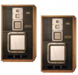
Sony speakers:
Attachments
"is the acoustic phase suppressed by a thin but long organ pipe?"
The organ pipe is physically long, but the its sound emitting area is near point source (wavelength relataed).
But, the instruments are etalons - per definitionem - , not reproductors. If they create sound by "acoustic phase suppression", then must be reproduce THIS perfectly...
The organ pipe is physically long, but the its sound emitting area is near point source (wavelength relataed).
But, the instruments are etalons - per definitionem - , not reproductors. If they create sound by "acoustic phase suppression", then must be reproduce THIS perfectly...
Is this some kind of play on words?
Calvin wrote above in the post - "A 25cm wide panel suffers from phase cancellation from below 800Hz already".
But at the same time, he did not indicate what the length of the panel is, but it can be 10cm.?
Of course, musical instruments are a "standard by definition", well then let's say not only reproductions of their bodies of the same physical size, but also the material from which these instruments are made, for example, a violin must be repeated with a speaker made of striped maple and spruce, a flute made of silver, the clarinet is made of ebony ... but trying to repeat all this variety with a piece of cardboard or film is impossible but priori.
Of course, when I wrote about a good combination of low-frequency and high-frequency planar bands, I meant in comparison, for example, two speakers, of which one is a dome, and the second is a cone or something similar, that is, in comparison with other similar sound reconstruction options.
And of course, we will reach a dead end when we begin to equate the shoulder and lever strike with a mallet of a big uncle on the same big drum with a speaker enclosed in a box glued from sawdust, but at the same time one of us will say, wait, this is impossible, the size of the diffuser does not answer the size of the drum membrane, and this paper diffuser is not activated correctly, you need to hit it with a lever strike of the mallet, then it will make the right sound 🙂
I would even say more - all low-frequency acoustic musical instruments suffer from a similar disease except for the organ.
The double bass, contrabassoon or tuba do not correspond with their range of extracted notes to the size of the physical body of the instruments themselves. Therefore, these musical instruments play with harmonics, but not with fundamental tones.
And only in large pipes of the organ, the length of the pipe corresponds to the wavelength of the fundamental tone of the notes being played.
Last edited:
Hi,
"Ok, then please answer, is the acoustic phase suppressed by a thin but long organ pipe?"
No, I won't, because a organ pipe has nothing to do with the problem here.
One can calculate the effect of acoustic phase cancellation and the associated drop in SPL.
Almost any paper dealing with electrostats talks about this problem and some even provide for the physical formulas, e.g. Peter Baxandall.
The example of the tall (>1m) 25cm wide panel was just given, as the drop in SPL is already noticeable at 600Hz, the xover frequency stated for the 2cm wide strip.
Such a thin strip will show serious acoustic phase cancellation at much higher frequencies.
So either you equalize the SPL drop heavily or You accept a very non-constant amplitude response.
Acoustic phase cancellation is just a matter of the size and shape of the driver membrane and the way its mounted (in an frame/open baffle or a more or less closed casing).
The type of driver or the type of motor doesn't play a role here.
jauu
Calvin
@havun : Just a brief feedback to say thanks for your reply to my question. I perceive that you are quite content with your solution - which is an attractive feat, indeed 😉 .
@Calvin : Although I do not see your replies particularly related to my question I nevertheless appreciate your chiming in with your insights & knowledge about this. Good information & feedback ...
Have a good day both of you ... Jesper
@Calvin : Although I do not see your replies particularly related to my question I nevertheless appreciate your chiming in with your insights & knowledge about this. Good information & feedback ...
Have a good day both of you ... Jesper

Hi guys.
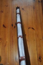
Already here I wrote that from the very beginning I planned to supplement this strip (20mm-1900mm) with acoustic design and of course I tried its return without acoustic design and with it.
So, when the strip itself is suspended evenly stretched from top to bottom, it practically does not play at all, that is, it plays very, very quietly even at those frequencies that correspond to its physical size.
But!, when it is bent vertically, the return at these frequencies increases several times.
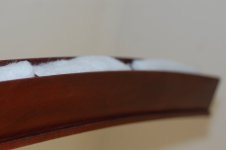
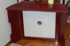
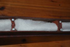
And if it is placed in a wooden case of the "open box" type and filled with padding polyester, then it is generally excellent, that is, it works down to 600 Hz.
Without filling with synthetic winterizer, a hump appears in the Amplitude Frequency Response at the lower frequency (it is perceived by ear as a high wolf howl).
Just as you will notice in the photo, there is a small horn in the wooden case.
All this in a complex, namely, the vertical curvature, the acoustic design of the "open box" type and the horn gives that increase in sensitivity and expansion of the range down, which I described here at the very beginning of the topic.
So there are no tricks in this, but there is a rational explanation 🙂.
I also made a horn for the subwoofer, it is customizable, I will write about it later.
Already here I wrote that from the very beginning I planned to supplement this strip (20mm-1900mm) with acoustic design and of course I tried its return without acoustic design and with it.
So, when the strip itself is suspended evenly stretched from top to bottom, it practically does not play at all, that is, it plays very, very quietly even at those frequencies that correspond to its physical size.
But!, when it is bent vertically, the return at these frequencies increases several times.
And if it is placed in a wooden case of the "open box" type and filled with padding polyester, then it is generally excellent, that is, it works down to 600 Hz.
Without filling with synthetic winterizer, a hump appears in the Amplitude Frequency Response at the lower frequency (it is perceived by ear as a high wolf howl).
Just as you will notice in the photo, there is a small horn in the wooden case.
All this in a complex, namely, the vertical curvature, the acoustic design of the "open box" type and the horn gives that increase in sensitivity and expansion of the range down, which I described here at the very beginning of the topic.
So there are no tricks in this, but there is a rational explanation 🙂.
I also made a horn for the subwoofer, it is customizable, I will write about it later.
Attachments

I made measurements of the amplitude frequency response from the LISTENING PLACE, and this is 3 meters from the speakers to the sofa 🙂
The microphone was at the level of my head.
That is, everything is like in life.
But the sound card of this laptop overwhelms the low-frequency region, a little later I will install the program on a computer where this will not happen and I will take measurements again.
The microphone was at the level of my head.
That is, everything is like in life.
But the sound card of this laptop overwhelms the low-frequency region, a little later I will install the program on a computer where this will not happen and I will take measurements again.
Attachments


@havun : ... Hi again ..
Might I ask you ... So, just to get a clearer understanding of how the HF unit is made: You have a strip of bronze mesh at the front surrounded by a slightly horn-shaped wooden structure. And, then, behind the bronze mesh you have some damping material - and then the wooden structure is closed at the back so that the transducer itself (bronze-membrane-bronze) is mounted in a closed enclosure. Do I understand this correctly - or did I miss something?
Cheers,
Jesper
No, it's a little wrong, there is exactly an OPEN box, behind the driver there is a certain volume that is filled with padding polyester.@havun : ... Hi again ..
Might I ask you ... So, just to get a clearer understanding of how the HF unit is made: You have a strip of bronze mesh at the front surrounded by a slightly horn-shaped wooden structure. And, then, behind the bronze mesh you have some damping material - and then the wooden structure is closed at the back so that the transducer itself (bronze-membrane-bronze) is mounted in a closed enclosure. Do I understand this correctly - or did I miss something?
Cheers,
Jesper
This is such an acoustic design, there is a closed box, there is a phase inverter, a labyrinth, and there is an open box, and so I have an open box, it is not hermetically sealed. But the synthetic winterizer material (like cotton wool is only lighter) in order to "lubricate" the main resonance of the panel and load the membrane acoustically.
Hello.
 ... Anyway, still interesting and I will be following the thread on & off as time allows. Wishing you a pleasant day
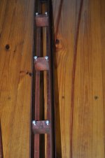
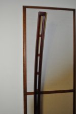
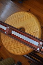
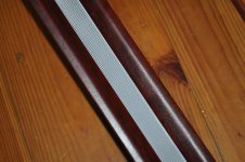
 Today I worked a lot from the very morning, namely, I dismantled my high-frequency drivers and painted bronze stators with acrylic car paint in three layers. But for this I had to remove the old membranes and make new ones, since they are glued to the stator insulators, white plastic insulators and they are non-removable. I also isolated everything more carefully.Where the screws enter the wooden blocks, metal nuts are pressed on the back side and in this way the driver's sandwich is pressed through thin wooden planks along the entire length of the wooden case.
I did this (painted) to isolate the stators so that I could give more signal and not be afraid of a breakdown.
I took a few photos of how the driver works:
I did this (painted) to isolate the stators so that I could give more signal and not be afraid of a breakdown.
I took a few photos of how the driver works:
Attachments

Last edited:
Very nice woodframe!
Has the stator insulator a bit of leaky character (for example PVC at Audiostatic or carbon black added powder coating at Final)?
Has the stator insulator a bit of leaky character (for example PVC at Audiostatic or carbon black added powder coating at Final)?
Hi Havun .. thanks for posting the pictures - I think I am now able to visualize what they look like in detail  ... One question, though, just to make sure: On the pictures it doesn't look as if there's any kind of plate attached to the backside of the wooden frame - is that correct? That is, you have a structure being ... stator-membrane-stator-damping material-open back .. which is surrounded by the u-shaped wooden frame with a slight horn-loading on the front?
Would that be correct?
Cheers, Jesper
P.S.: BTW, Yup, it is fine woodword .. 🙂
... One question, though, just to make sure: On the pictures it doesn't look as if there's any kind of plate attached to the backside of the wooden frame - is that correct? That is, you have a structure being ... stator-membrane-stator-damping material-open back .. which is surrounded by the u-shaped wooden frame with a slight horn-loading on the front?Would that be correct?
Cheers, Jesper
P.S.: BTW, Yup, it is fine woodword .. 🙂
I understood what you mean, in the very first columns (very large in area, they are here in the topic) I used black paint, the color pigment of which included an electrically conductive material (very high-density), in its action it was equated to some the proportion of soot in the paint on the stators.Very nice woodframe!
Has the stator insulator a bit of leaky character (for example PVC at Audiostatic or carbon black added powder coating at Final)?
But, to be honest, I did not notice any striking difference between this paint and ordinary acrylic paint 🙂, but acrylic paint is good because it dries quickly. Therefore, I did not bother.
Yes, that's exactly how it is.Hi Havun .. thanks for posting the pictures - I think I am now able to visualize what they look like in detail
Would that be correct?
Cheers, Jesper
P.S.: BTW, Yup, it is fine woodword .. 🙂

- Home
- Loudspeakers
- Planars & Exotics
- Full-range, two-way ESL