There are several changes to the current state of the audio system.
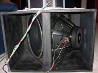
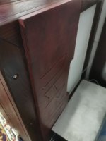
Firstly, I finally got rid of a couple of parasitic resonances in the mid-bass register by installing a memory form tape on the back of the bass segment, it divided the radiating panel at the back into two equal parts, I don’t know how this affected the destruction of the resonance, perhaps due to the physical size rear panels 50/50cm. divided into two 20 cm each.))). In general, this is an empirical decision, not fully realized.
Next about the amplifier, I received from the author of the product two new modules with an output load impedance of 1 Ohm, which I needed for RF drivers.
This guy also developed new power supplies specifically for these amplifier modules, previously I used Chinese ones from Aliexpress, they were too noisy and got incredibly hot, for them I made a huge battery of cooling radiators, now, with the new power supplies, the radiators are completely cold, now they are serve as decoration))).
As for the connecting cables, I made all the connecting cables, starting from the head of the vinyl player and ending with all the rest, from mono strands of silver of the highest standard (999.9%) and screened everything very high quality, I bought the silver in a specialized store for jewelers.
The sound with noble silver is absolutely clear and realistic, it immediately caught my eye.
Attachments
-
![IMG_20231120_112547[1].jpg](/community/data/attachments/1188/1188998-a628912b79b1a43c357c68ec5b5150d5.jpg?hash=piiRK3mxpD) IMG_20231120_112547[1].jpg361.4 KB · Views: 156
IMG_20231120_112547[1].jpg361.4 KB · Views: 156 -
![IMG_20240301_111303[1].jpg](/community/data/attachments/1188/1188999-c842ead4eeea5433fe36f55ad04039bc.jpg?hash=yELq1O7qVD) IMG_20240301_111303[1].jpg236.7 KB · Views: 149
IMG_20240301_111303[1].jpg236.7 KB · Views: 149 -
![IMG_20240219_121905[1].jpg](/community/data/attachments/1189/1189000-6592a8a23cccd5f0398bea922511115b.jpg?hash=ZZKoojzM1f) IMG_20240219_121905[1].jpg366.8 KB · Views: 155
IMG_20240219_121905[1].jpg366.8 KB · Views: 155 -
![IMG_20240224_093150[1].jpg](/community/data/attachments/1189/1189001-36bd46e7aedf1f38d5c891ea9d0bbe84.jpg?hash=Nr1G567fHz) IMG_20240224_093150[1].jpg231.1 KB · Views: 155
IMG_20240224_093150[1].jpg231.1 KB · Views: 155 -
![IMG_20240301_111501[1].jpg](/community/data/attachments/1189/1189002-58b1cd63f0b87e66f2607f1ddb479616.jpg?hash=WLHNY_C4fm) IMG_20240301_111501[1].jpg315.5 KB · Views: 149
IMG_20240301_111501[1].jpg315.5 KB · Views: 149 -
![IMG_20240301_111512[1].jpg](/community/data/attachments/1189/1189003-a3d914bced032b1cee91005b5eac7d57.jpg?hash=o9kUvO0DKx) IMG_20240301_111512[1].jpg323.6 KB · Views: 146
IMG_20240301_111512[1].jpg323.6 KB · Views: 146 -
![IMG_20240301_111533[1].jpg](/community/data/attachments/1189/1189004-398b90232818c1ee6bf8158b152932a8.jpg?hash=OYuQIygYwe) IMG_20240301_111533[1].jpg289.1 KB · Views: 146
IMG_20240301_111533[1].jpg289.1 KB · Views: 146 -
![IMG_20240227_004541[1].jpg](/community/data/attachments/1189/1189006-f31d58c4419830bdff4a6c6b125d02ed.jpg?hash=8x1YxEGYML) IMG_20240227_004541[1].jpg261.9 KB · Views: 135
IMG_20240227_004541[1].jpg261.9 KB · Views: 135 -
![IMG_20240227_004655[1].jpg](/community/data/attachments/1189/1189007-1e12ae718f5401a66fb26cf3f17d75f7.jpg?hash=HhKucY9UAa) IMG_20240227_004655[1].jpg327.8 KB · Views: 142
IMG_20240227_004655[1].jpg327.8 KB · Views: 142

Did you try this subwoofer with additional flat baffle (I think, at measure, bigger distance)?
Last edited:
Of course I tried, I put a spacer between two packages (each with 3 membranes and 4 stators), with a distance of 10 to 20 cm, and even made the effect of a slightly open book (here it is at the beginning of the thread), then I was looking for how to get rid of the pronounced resonance of 136Hz and its highest harmonics, I even bought a parametric equalizer then to accurately influence this frequency, but the equalizer was digital, and I listen to analogue as well, and this was a contradiction 🙂.
Next, I looked for how to empirically get rid of parasitic resonances and slowly began to feel for it and yes, I continue to do so.
Next, I looked for how to empirically get rid of parasitic resonances and slowly began to feel for it and yes, I continue to do so.
Esoterics and randomization matter.
I placed a plywood panel on the front of the bass segment with the inscription of the Slovenian god of thunder Perun and suddenly!!!
There was a thunderous sound😆:
I placed a plywood panel on the front of the bass segment with the inscription of the Slovenian god of thunder Perun and suddenly!!!
There was a thunderous sound😆:
Did some more experiments and measurements.
Manipulations with a piece of plywood, which I put in different places of the bass driver led to the disappearance of a couple of parasitic resonances, which was indicated by measurements in the listening position on the sofa, because the microphone was installed on it, and not in one meter or 30 cm from the driver itself. Although this search lasted long enough, as I wrote here I even tried to apply different equalizers (graphic and parametric), but eventually abandoned them completely.
At the moment the signal from the sound source goes through a Canton preamplifier, an active crossover (two-way) and a class "D" power amplifier.
I will say a few words about the safety of electrostatics, although I was warned by the moderator of the forum (in connection with the rules), that if I once again raise this topic it will be the last time, then apparently he will ban me forever, but still I will raise this topic.
What the user of electrostatics(?) needs to know is that you can touch one stator with your hand if you are on an insulating material, that is, if you are standing on a wooden floor or some other floor that is not directly connected to the Earth.
It is also strictly forbidden to touch two stators located at the front and rear of the driver at the same time.
Since I have dealt with electrostatics not theoretically, as many here, but practically and built them for 12 years, I make this statement responsibly, as well as demonstrate it on the video clip, which in one of the topics here on the forum moderator deleted as life-threatening. But listen, so it is possible to come to the fact that ban sockets for electricity, there is also high voltage and if you stick two fingers in the socket, it may not be good, so we need to know what can be done and what can not be done.
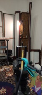
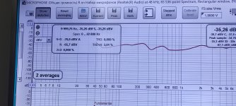
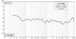
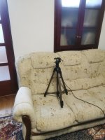
The frequency response graph shows a rise in frequencies in the region of the main resonance of the room, as well as in the region of the highest frequencies (18 kHz), since the microphone is installed on the sofa where I sit while listening to music, then my calculation of a vertically curved HF driver whose sound from a distance works here does not get lost, as in a conventional driver, but rather focuses and comes to the ear without loss.
Let me remind you that the HF driver is curved with a radius of 3 meters and this is exactly the distance from the driver to the seat on the sofa.
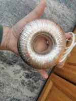
I am attaching a photo of a toroidal step-up transformer made in the village of Velykye Kurylivtsy, Vinnytsia region (Ukraine), I gave them technical specifications and they made the first ones back in 2012, then I ordered the same ones from them several more times, they turned out to be very successful for the bass driver (transformation coefficient 1:200)
Manipulations with a piece of plywood, which I put in different places of the bass driver led to the disappearance of a couple of parasitic resonances, which was indicated by measurements in the listening position on the sofa, because the microphone was installed on it, and not in one meter or 30 cm from the driver itself. Although this search lasted long enough, as I wrote here I even tried to apply different equalizers (graphic and parametric), but eventually abandoned them completely.
At the moment the signal from the sound source goes through a Canton preamplifier, an active crossover (two-way) and a class "D" power amplifier.
I will say a few words about the safety of electrostatics, although I was warned by the moderator of the forum (in connection with the rules), that if I once again raise this topic it will be the last time, then apparently he will ban me forever, but still I will raise this topic.
What the user of electrostatics(?) needs to know is that you can touch one stator with your hand if you are on an insulating material, that is, if you are standing on a wooden floor or some other floor that is not directly connected to the Earth.
It is also strictly forbidden to touch two stators located at the front and rear of the driver at the same time.
Since I have dealt with electrostatics not theoretically, as many here, but practically and built them for 12 years, I make this statement responsibly, as well as demonstrate it on the video clip, which in one of the topics here on the forum moderator deleted as life-threatening. But listen, so it is possible to come to the fact that ban sockets for electricity, there is also high voltage and if you stick two fingers in the socket, it may not be good, so we need to know what can be done and what can not be done.
The frequency response graph shows a rise in frequencies in the region of the main resonance of the room, as well as in the region of the highest frequencies (18 kHz), since the microphone is installed on the sofa where I sit while listening to music, then my calculation of a vertically curved HF driver whose sound from a distance works here does not get lost, as in a conventional driver, but rather focuses and comes to the ear without loss.
Let me remind you that the HF driver is curved with a radius of 3 meters and this is exactly the distance from the driver to the seat on the sofa.
I am attaching a photo of a toroidal step-up transformer made in the village of Velykye Kurylivtsy, Vinnytsia region (Ukraine), I gave them technical specifications and they made the first ones back in 2012, then I ordered the same ones from them several more times, they turned out to be very successful for the bass driver (transformation coefficient 1:200)
Attachments
Last edited:
Hi, it looks like an interesting build with excellent results. I'm curious about the bass unit construction and I am hoping you could provide me with some further insights.:
Why is there a big hole in the middle of the stator ?
Did you progressively increase the spacing between each static / diaphragm ?
For the Stator, what gauge thickness / hole size / % open did you go for, and what would recommend (if different) for a rebuild. My concern would be with the stator not being stiff enough over a long span.
What thickness membranes did you use in the bass, was wondering how challenging it would be to get the right stretch on a wide span ?; 20Hz is very impressive
Did you take any photos during the construction phase? Would be great to see them 🙂
Best wishes
Dave
Hello, this project was preceded by another project with huge dimensions, a photo of it is here in the topic.
Therefore, this second project was a consequence of the first, from which I learned the corresponding lessons.
First, I made drivers with three membranes and four stators and placed them in ash boxes, listened to them and it seemed to me that the bass effect was not enough, not what I expected. And then the idea came to connect them together with clamps and listen to what happened, it gave its effect. But then I postponed everything for several years because I took up a commercial project of electrostatic headphones. Then I again reactivated the speakers and made another set of housings and stators to create a second stereo channel.
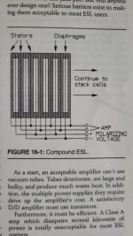
By design, the stators are cut from perforated steel 3mm thick, they are very rigid and heavy (I learned this from a previous project where the stators were 1mm thick.).
The acoustic transparency of the perforation and the stator metal body is approximately 50/50.
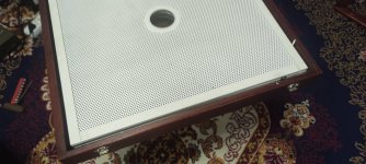
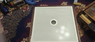
The hole (70mm) in the center of the stator was originally intended to supply the highest possible polarizing voltage to the membrane and the membrane would not stick to the stator since the center (where the greatest attraction) would be unloaded and thus increase the separation (sensitivity) of the drivers.
The film thickness in the bass driver is 15 microns.
I'll add it later.
Therefore, this second project was a consequence of the first, from which I learned the corresponding lessons.
First, I made drivers with three membranes and four stators and placed them in ash boxes, listened to them and it seemed to me that the bass effect was not enough, not what I expected. And then the idea came to connect them together with clamps and listen to what happened, it gave its effect. But then I postponed everything for several years because I took up a commercial project of electrostatic headphones. Then I again reactivated the speakers and made another set of housings and stators to create a second stereo channel.
By design, the stators are cut from perforated steel 3mm thick, they are very rigid and heavy (I learned this from a previous project where the stators were 1mm thick.).
The acoustic transparency of the perforation and the stator metal body is approximately 50/50.
The hole (70mm) in the center of the stator was originally intended to supply the highest possible polarizing voltage to the membrane and the membrane would not stick to the stator since the center (where the greatest attraction) would be unloaded and thus increase the separation (sensitivity) of the drivers.
The film thickness in the bass driver is 15 microns.
I'll add it later.
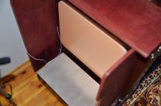
Thoughts are swarming like bees, I want to try to make a passive radiator behind my subs, I couldn’t think of anything better as a membrane like high-density foam plastic (the one that is placed on the floor as insulation).
The suspension will be made of genuine leather (the best damping material).
The suspension will be made of genuine leather (the best damping material).
Attachments
![IMG_20240718_134006[1].jpg](/community/data/attachments/1243/1243006-e4be7cf868aa0694e4628b7491f42024.jpg?hash=5L58-GiqBp)
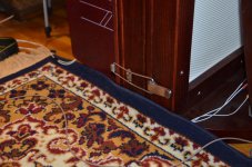
The process is very delicate and requires a lot of attention, but today I have to listen to this.
I remembered one of my old friends, he always said the following - if I started making speakers this morning, then by this evening I should finish them and listen and enjoy the whole evening with a glass of beer.
I remembered one of my old friends, he always said the following - if I started making speakers this morning, then by this evening I should finish them and listen and enjoy the whole evening with a glass of beer.
Attachments
![IMG_20240718_135806[1].jpg](/community/data/attachments/1243/1243010-b95b38fa07df3f4c632548db435e1d5d.jpg?hash=uVs4-gffP0)
As I wrote, by the evening everything was ready and listened to.
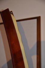
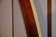
It cannot be said that the entire range of frequencies emitted to the rear has disappeared, no, part of it remains, but the part that has little effect on the stereo effect.
The stereo became more enlightened, that is, the signal that followed the direct signal became more suppressed and from this the stereo picture improved, but this is a side effect, the main thing I wanted to pay attention to was the quality of the low frequencies, the low frequencies became extremely damper, regardless of the color of the room and its the influence of low frequencies has become the same as in good headphones, that is, very detailed, without loops that form the room + speakers.
Attachments
![IMG_20240719_113952[1].jpg](/community/data/attachments/1243/1243383-d78d3ebbebeae10b1bb41dacd4305b65.jpg?hash=140-u-vq4Q)
![IMG_20240719_114025[1].jpg](/community/data/attachments/1243/1243386-f494f5cae87ad38ace3d321dda0e3526.jpg?hash=9JT1yuh604)
![IMG_20240719_114056[1].jpg](/community/data/attachments/1243/1243387-7f6d8998801fa529cc7dd920281340f8.jpg?hash=f22JmIAfpS)
![IMG_20240719_114208[1].jpg](/community/data/attachments/1243/1243389-46e56d9851fb1e64350a21560ec2640a.jpg?hash=RuVtmFH7Hm)
![IMG_20240718_164050[1].jpg](/community/data/attachments/1243/1243390-aa3b085ebe9e1a3d7a10a399b3a1618e.jpg?hash=qjsIXr6eGj)
Hello,The speakers consist of a bass segment, which in turn is built of a double membrane stack, each with 4 stators and 3 membranes, a total of 6 membranes and 8 stators composed by isobaric.
impressing project ! Do you use the same foil/stator spacing throughout the stack ?
For an application like this, it will be 5mm ? The spacers made of polymer bars ? Two polarizing supply~6kV ?
I read in your thread you now covered the whole satck with front/back foils :
Here I can give a comment based on my Dayton Wright experience.
The DW speakers also are covered with two outer foils. The distance between the front foil to the ELS cells behind is a lot lower than the back outer foil. The air volume at the front is about 1/4 of the backside volume ( I read it somewhere from Mike Wright ). Whell, in the DW there is a heavy gas included, but the welcome effect is a kind of "bassreflex boost". This means, there is a very low frequency range, where front - and back outer foil oscillate in phase. This should work without gas in the same whay...more volume needed..
regards, Philipp
Attachments
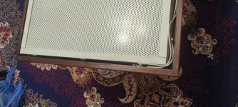
Hi, I have already written here that the subwoofer consists of two blocks, each with 3 membranes and 4 stators, the distance between the stator and the membrane is 3 mm. The insulators are made of white plastic.
The distance between the blocks is 30 mm, the blocks are pulled together with frog ties. They can be disassembled and configured differently.
Polarizing voltage of two types, plus 5 kV and minus 5 kV. That is, plus is supplied to the first membrane, minus to the second, plus to the third, etc.
I tried to put films on the outside, but then I discovered that they compress the low-frequency signal and refused.
Then it seemed to me that the passive radiator at the back should be rigid and hold its shape, and not in the form of a bending film, and this gave a result, I recommend this for use in planars.
In general, I have tried many things in these subwoofers, a closed box and even a pseudo megaphone. But what is now is the most correct for me, that is, in my room.
Many times I have already tried the influence of the rear part (rear) of the emitter on the formation of the sound phase, at some time it seemed that it brings happiness, but this time I was convinced that it does not.
If this happened in natural conditions, then this is normal, but we are dealing with a stereo format, where two sound sources form non-existent sound sources, imaginary and the presence of sounds coming to the back wall, and then turning and catching up with the direct sound in a small room - do dirty tricks, blur the stereo picture and the accuracy of timbres.
In short, I decided to completely block the sound from the HF driver and stuffed the foam rubber into the small volume of the HF driver box.
Of the innovations, I also remade the loops - ties that pull together two LF drivers + "my diffuser"😛.
As a result, the stereo picture became deeper and much more accurate, and the bass with "my diffuser" is rounded and mercury.
Attachments
I disassembled my bass drivers to make sure that everything is OK with the diaphragms, there were cases when I accidentally gave them a very heavy load when switching inputs to the amplifier.
But everything is OK, the diaphragms are in pristine condition.
Also I tried to make a primitive Hale of three segments, two of which are active and the third is passive, it turned out to be very cool, I did not expect.
I'll have to think about how to domesticate it.
The hale turned out to be in the form of an open book.
Attachments
![IMG_20241008_193802[1].jpg](/community/data/attachments/1273/1273318-f022e29e0b96812bc6d63dffa7a992b6.jpg?hash=dvyugVp32G)
![IMG_20241008_193832[1].jpg](/community/data/attachments/1273/1273319-eaeb81b343375fdf628da9a43cd2e8c4.jpg?hash=fWY6x9zdww)
- Home
- Loudspeakers
- Planars & Exotics
- Full-range, two-way ESL