Hi,
if the ESL panels are designed for efficiency - and efficiency is THE mantra for ESLS- then one doesn´t need powerful amps.
What You need are stable amps, capable to drive a highly complex load.
My ´small´ panel was measured with 110dB@4m, at a power level of roundabout 50W.
Still thoug the big Crown Reference amp (about 600W iIrc) was almost boiling in his attempt to handle the considerable imaginary current.
A 20W KR Audio SE triode connected to the same panel on the other hand had no issues at all to drive this load to ear splitting levels as well .... and sounding much better also.
And don´t overestimate direct drive amps. It´s really hard to design an kV-Amp that betters a well executed tranny.
A ESL-headphone amp is by far an easier task and can´t be compared to a an amp designed for a large panel.
Designs like the Acoustat amp can only drive segmented low-capacitance panels and seemingly every second part in that amp is needed for some compensation means .... sounding quite mediocre accordingly.
jauu
Calvin

Hi.
Thank you very much for the recommendations and explanations.
I use a powerful 200 watt amplifier.
It has a tube preamplifier and a transistor power amplifier (on modern field-effect transistors).
It is enough for my needs, it works 30 watt in class "A" and the rest of the power in class "A + B".
Half of its power is enough for me, it is very loud.
You said that not always the direct drive is better than the transformer, unfortunately I could not try it on the speakers for lack of direct drive.
But on the headphones quite well you can hear how the transformer loses to the direct drive first of all in the lower frequencies.
That's why I thought that exactly in the lower frequencies, because I don't have a speaker with magnets and a coil there, I can get a gain in energy and sound pressure, all the same transformer sound in this range is a bit slow and amorphous in the headphone tract, and therefore the same in the speakers.
But maybe it is only in my imagination 🙂 .
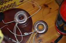
I mentioned here that earlier 7 years ago I had only one subwoofer ready and I connected two step-up transformers, making the connection in series-parallel, which means the transformation ratio was not 200, but 400 times.This sounds excellent. Congratulations. Can you post some more clips please?
The spectrum of the plucked double bass intro in your youtube clip shows very clean peaks. Looks like your ESL bass panel design does great impulse. Gives that dynamic live sound:
View attachment 1009939
Dynamic range analysis = 15 !
View attachment 1009940
Hence the energetic double bass.
A couple of days ago I did the same thing, but with two subwoofers and four bass transformers.
My conclusion is this - guys, do not spare the iron and copper transformers if you do bass step-up transformers 🙂 .
Attachments
Very creative design. Thanks for sharing the photo and the sound 🙂

Hi Havun,
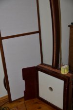
thanks for sharing your story about these creative stats! I really like your woodworking skills and the non standard design.
I've never thought about generating esl low frequencies using an isobaric esl configuration. If I'm correct one woofer / channel uses six diaphragms? The problem I foresee is a rather high fundamental resonant frequency because of the rather small area compared to a single diaphragm, which limits low frequency range. Not sure if my idea is correct?
...or would multiple isobaric configurated diaphragms lower fundamental resonance as the coupled air increases so fundamental resonant frequency decreases?
There was already such a bent design to produce, I suppose, higher sound pressure. Sectioned ESL. Curios ones may waste time using G...E.
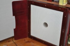
The frequency of a single 50/50cm membrane is very low. But with a set of six membranes, it rises. This problem was partially solved by acoustic loading between two packages (the photo shows how two packages have the shape of an ajar book. The natural resonance of such a construction cannot be considered in isolation from its coordination with the acoustics of the room, they have a direct connection. Of course, such a package in the open field will behave completely differently.Hi Havun,
thanks for sharing your story about these creative stats! I really like your woodworking skills and the non standard design.
I've never thought about generating esl low frequencies using an isobaric esl configuration. If I'm correct one woofer / channel uses six diaphragms? The problem I foresee is a rather high fundamental resonant frequency because of the rather small area compared to a single diaphragm, which limits low frequency range. Not sure if my idea is correct?
In this case, not only to increase the sound pressure, but also for a higher accuracy of the arrival of high frequencies in TIME.There was already such a bent design to produce, I suppose, higher sound pressure. Sectioned ESL. Curios ones may waste time using G...E.
That is quite impressive output!... My ´small´ panel was measured with 110dB@4m, at a power level of roundabout 50W.

Can you provide a few more details so we can better understand how this was measured and accomplished?
- was this the small panel you mention in another threads as being 125x25cm driven with simple power toroid pairs of 230V/6V?
- by 50W do you mean 50W into 8ohm = 20Vrms applied to toroid pair = 1500Vrms at stators?
- was this for a single panel or a pair of panels?
- was this RTA room type response? Or anechoic windowed impulse test.
- over what frequency range was the 110dB achievable?
Hi,
the measurements took place about 2008 iIrc.
I don't renember every detail, but I try.
The measurements took place in the anechoic room of the RWTH Aachen (Aachen university).
Prof. Anselm Goertz used the MonkeyForest analyzer system developed by him at Aachen university.
The system allows for windowed measurements.
Mik was a freshly calibrated B&K 41something (4193?), laid down on the floor to omit with boundary reflections.
As amp he tried a few, finally ending up with a big 600W Crown.
The 'small' ESL utilized its integrated pair of 150W class-D amps.
Both ESLs and both of the pairs were measured single.
Measurement freq range was fullrange of the complete speakers, which means ranges of >150Hz, resp. >200Hz for the different panels involved (xovered).
When taking the SPLmax measurement .... which he took twice, since he wouldn't believe an ESL to be able to play that loud ... he mentioned the 50W power figure which I think he estimated from the voltage and impedance plot.
In a computer crash later I lost almost all data over more than two years of work, amongst this most of my ESL files.
jauu
Calvin
This is entirely possible if certain conditions are met.
For example, the necessary conductive coating of the membrane, the proper design of the stators to prevent voltage breakdowns.
I was surprised that my high-frequency driver with a gap of 1 mm between the stator and the membrane withstands a polarizing voltage of 5 kilovolts on the membrane and at the same time there are no visible voltage breakdowns during operation, and this despite the fact that the stators of the bronze woven mesh are completely not covered with insulating varnish (I installed for myself that high frequencies are reproduced better with stators not covered with insulation), but the level of return has increased significantly.
Although they should work with a voltage of 2 kilovolts DC voltage to the membrane.
But there are several factors why this happens.
Hi friends.
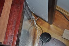
Since the thirst for creativity haunts, I decided to temporarily do what I had been planning for a long time, and for now, on the one hand, glue the film directly onto the subwoofer case to listen to how it affects the sound.
What is it in essence ?, an additional passive membrane attached an additional mass of air that is in a mobile state and not in the closed space of the box, this membrane is also absolutely transparent to the sound of all frequencies from the back of the radiator.
But!, this membrane is important to me as a damper of the main resonance of the entire subwoofer and ... it works.
Основной резонанс размазан, НЕ торчит отдельным, ярко выраженным пиком настолько, что мне даже эквалайзер не нужен, но я все же оставил эквалайзер для отбивания самых низких частот (20Гц) выдаваемых парой трансформаторов с коэффициентом трансформации 1:400, чтобы не перегружать мембраны упаковки и не приводить к вспышкам высокого напряжения.
I remembered why Kvod makes such passive membranes on both sides and this is not at all to protect against dust, or rather not in the first place, but in order to smear the main resonance.
Dust protection is just a bonus because Martin Logan doesn't install any dust protection and their speakers have been running great for decades.
Attachments
Last edited:
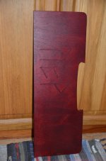
In short, I made two cheeks for each subwoofer imitating a horn, they are adjustable in terms of the opening angle of the horn.
This gives some increase in the general, subjective energy at certain frequencies, namely in the mid-bass.
I also connected the subwoofers to a separate amplifier, this is definitely better, but the amplifier is rather weak.
Until I connect it with battery power (36 volts, 48A.h.)
This gives some increase in the general, subjective energy at certain frequencies, namely in the mid-bass.
I also connected the subwoofers to a separate amplifier, this is definitely better, but the amplifier is rather weak.
Until I connect it with battery power (36 volts, 48A.h.)
Attachments
@havun: Hi 😉 ...
I have seen and been thinking about your curved & narrow ESL design and wonder if you can just briefly describe "how" you find it to sound differently (better) than a large surface ESL? My personal thought about it (and it is a thought, obviously) is that it could have a quite good dispersion in the horisontal plane, as well as a wide area of optimum/quite good listening positions, however, how is the integration between the two drive units? Is it tonally "neutral/balanced" or do you find that there are either advantages or disadvantages tonally (or in some other respect) with this design ... ?
You may have mentioned this before - I just don't remember reading about it - but would appreciate just a brief outline of this if that is ok with you ...
Have a good day,
Jesper
Hey Jesper.
Of course, we are here to share opinions.
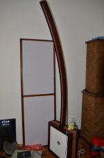
I've tried many different forms of electrostatic drivers and this is exactly what I came up with.
First of all, its clear advantage is that in the horizontal plane it is only 20mm.
And we remember well that the sound wave length of 20 mm is 16 kHz. That is, in this case, the range up to 16 kHz will NOT have sound directionality, but is broadly directed up to 16 kHz. And this, in turn, means that the sound does not have a specific sound color with such a directivity of sound, but is tonally correct (smooth).
But!, we also remember well that an electrostatic is an insensitive emitter and it needs a large radiation area to compensate for this.
To do this, I bent a long tape of the emitter (1900 mm.) In a vertical plane and thus collected the sound from the entire length of the tape and fed it to the listener in the same time mode, that is, the sound comes at the same time from the middle of the emitter and its edges and thus, a point source of sound is realized here, although in practice it is elongated in vertical space.
In my subjective opinion, such a transducer is the most accurate and true of all that I have ever done in the field of medium and high frequencies, and I have tried straight and curved (a la Martin Logan) forms.
Of course, we are here to share opinions.
I've tried many different forms of electrostatic drivers and this is exactly what I came up with.
First of all, its clear advantage is that in the horizontal plane it is only 20mm.
And we remember well that the sound wave length of 20 mm is 16 kHz. That is, in this case, the range up to 16 kHz will NOT have sound directionality, but is broadly directed up to 16 kHz. And this, in turn, means that the sound does not have a specific sound color with such a directivity of sound, but is tonally correct (smooth).
But!, we also remember well that an electrostatic is an insensitive emitter and it needs a large radiation area to compensate for this.
To do this, I bent a long tape of the emitter (1900 mm.) In a vertical plane and thus collected the sound from the entire length of the tape and fed it to the listener in the same time mode, that is, the sound comes at the same time from the middle of the emitter and its edges and thus, a point source of sound is realized here, although in practice it is elongated in vertical space.
In my subjective opinion, such a transducer is the most accurate and true of all that I have ever done in the field of medium and high frequencies, and I have tried straight and curved (a la Martin Logan) forms.
Hi Havun ... & thanks for your feedback 😉
To me it is a really interesting approach not least because I reckon the "HF unit" is also relatively low capacitance and thus would be "easy" on the amplifier and possibly allow for good transformers (upper frequency extension). One question, though: How do you perceive the integration between the two drive units? I mean - they will have quite different dispersion characteristics - so do you also perceive their integration sound-wise to be "seamless" ... ?
Cheers - Jesper
- Home
- Loudspeakers
- Planars & Exotics
- Full-range, two-way ESL