The idea of a LTP is that the cathode load is so high that AC current can only travel from one of the pair to the other. By reducing the cathode resistance you allow a certain amount of the error signal (ie the difference in amplification between the two valves in the LTP) to force its way to ground. This translates to imbalance at the anodes since whatever the cathode does the anode follows and the cathodes are no longer perfectly coupled.
A Correctly functioning LTP takes the two valves amplification of the AC signal and averages the output such that the anodes signal becomes identical.
Using a Garter, with its relatively low cathode resistance, breaks this perfect AC balancing. The Garter is soley designed to address DC balance issues , by averaging the grid bias. This it does extremely well.
-------
The only issue I can see with the transistor Garter and RV schematic is that the interstage transformers resistance needs to be balanced perfectly otherwise the 0.7V sense voltage is liable to become swamped by the DC developed across the winding resistance. The resistor garters voltage will be much higher relative to the voltage developed across the secondary so will not be an issue. You may need to add resistance to balance the IT secondaries.
Shoog
good info
I have to think more about it
but still, what theoretically appears to be LTP, and what actually works like one may not be the same thing
I know such can be tricky, and most likely above my skills
I have read that there could be issues with dc on IT primary
at least there the Blumlein makes sense
I dont know, but resistor Blumlein has 2x 680ohm cathode resistors
Acitve Broskie version suggests 500ohm
1.2K or 500ohm, will that really make the big difference 😕 and then theres also a diode ?
all in all, maybe it will help to use balanced quality tubes (internally matched)
read that there could be some issues with ECC88, regarding higher distortion
and yeah, Revintage did suggest E88CC
maybe issues with ECC88 could be due to poorly balanced tubes, I dont know
I could consider 6N1P* or 6N23* instead
and still turning the coins
Using a proper LTP will make the need for matched drivers irrelivant. There are quite a few threads on tube LTP's on the board. The CCS is really simple (two transistors) and can be constructed and tested with a bench power supply. My last LTP CCS's are built on a 1"x2" perf board.
Shoog
Shoog
ok, lets leave the Blumlein where it is, and should be, at output
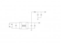
and I can see from lots of searching, CCS cathode bias on drivers might still be a sensible option
found this schematic
http://www.triodeguy.com/Triodeguy PDF files/6AS7 CURRENT BALANCED PP AMP SCH.pdf
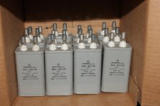
and, just remembered I have these NOS caps
found them a while ago, without knowing what to do with them
and I can see from lots of searching, CCS cathode bias on drivers might still be a sensible option
found this schematic
http://www.triodeguy.com/Triodeguy PDF files/6AS7 CURRENT BALANCED PP AMP SCH.pdf
and, just remembered I have these NOS caps
found them a while ago, without knowing what to do with them
Attachments
My good friend Revintage will be pulling his hairs when he sees this
Every time I am offered a fine scheme, things change again
well, so far just an idea
it "looses" one(two) expencive input line splitter trafo
and with a C3g even better drive
and no worries about balanced driver tubes
Every time I am offered a fine scheme, things change again
well, so far just an idea
it "looses" one(two) expencive input line splitter trafo
and with a C3g even better drive
and no worries about balanced driver tubes
Attachments
Forget about pentode driver if you don´t load the transformer hard either on the primary or the secondary side.
hey, nice to see you again
did you look at C3g specsheet, its not just any ordinary penthode
its supposed to be a good interstage driver, low impedance and high gain
I dont undertsand what you say about loading transformer harder
UL coupled makes a bigger cathode resistor possible, which is supposed to be a good thing, from what I understand
Sorry for the missunderstanding. As I said it is the pentode that needs loading not the tranny. Primary is recommended. Can be done with a resistor across the winding. Check Intactaudios forum where this discussed with D3a as driver.
as to why a penthode and interstage doesnt go well together.......
I have serached and searched and searched, and been through a hundred links to various sites, forums, and schematics
and found only one explaning
I get the feeling that its a penthode output stage that might not like interstage load
because, if it was the other way round, output trafos ought to presenet the same problem
I may ofcourse be wrong
and I found these two designs
Attachments
Who said they didn´t go well together😉? They do when properly loaded.
If you refer to poweramps they are as I earlier mentioned but with the load on the secondary.
If you refer to poweramps they are as I earlier mentioned but with the load on the secondary.
right, you did say that, yes
Im trying to figure how to wire that interstage (LL1660)
another good man with knowledge suggested to wire it in UL style
symmetric 50% wouldnt be hard, I guess
but Im trying to find a way to paralel some, and series other, on primary
but maybe it will give issues with the symmetric PP secondary, and result in unbalanced output
I dont know
my, this is slowly getting exotic
from what I understand, one good thing of doing interstage UL penthode driver is very high gain
the lowered gain through IT means even lower impedance
and even lower distortion
interstage specs ought to improve too
but maybe only in theory
could be taken even further with feedback, but I will try to avoid that problem
the lowered gain through IT means even lower impedance
and even lower distortion
interstage specs ought to improve too
but maybe only in theory
could be taken even further with feedback, but I will try to avoid that problem

Hi,
I built mine using a twin penthode as driver without IT with very good result.I can post the schematic if you don't mind.
Have Fun!
SS
I built mine using a twin penthode as driver without IT with very good result.I can post the schematic if you don't mind.
Have Fun!
SS
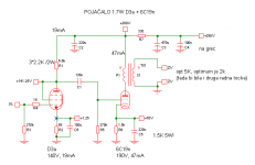
preliminary schematic
so far I understand that when triode coupled, plate(Ra) and inner resistance(Ri) are in paralel, which gives the desired low impedance
UL tapped through trafo they are still in paralel, I guess
but also with trafo impedance in series
well, I see the dilemma now 🙁
so far I understand that when triode coupled, plate(Ra) and inner resistance(Ri) are in paralel, which gives the desired low impedance
UL tapped through trafo they are still in paralel, I guess
but also with trafo impedance in series
well, I see the dilemma now 🙁
Attachments
Hi Tinitus !
Dont you think that you will get enough amplification with the driver tube in triodemode ?
The higher output resistance in UL will probably give you problems with the bandwith of the trafo.
Thorsten Larsen
Dont you think that you will get enough amplification with the driver tube in triodemode ?
The higher output resistance in UL will probably give you problems with the bandwith of the trafo.
Thorsten Larsen
Hi Tinitus !
Dont you think that you will get enough amplification with the driver tube in triodemode ?
probably, yes
but distortion doubles
UL tapped lowers gain and impedance, and thus even less distortion
and if accepting a small portion of step down from interstage, it may improve things a bit
but sure, I may be chasing a wild goose

and there is another way, like using a simple autoformer as phase splitter
I have seen that on Electraprint site
but then we are back to a cap coupled design
or parafeed
but then, some say choke or CCS load is useless with penthodes
and so it goes round and round
- Home
- Amplifiers
- Tubes / Valves
- ecc99 - 6C19n PP, (6S19P)