If an interstage was used then the low B+ on the driver wouldn't be an issue.
Shoog
from what I have read stated elsewhere the CCS does about the same thing
makes sense, since thats whats done to make this one work
IT is where we started
they cost money
but thats not the major issue
if IT really improved things I wouldnt mind the cost
but obviously the use of IT gave some issues with bias and grounding scheme
RC coupling seemed to result in a simpler design
worked well with the BlumleinGarter bias
and still simmed "exstremely well" 🙄
maybe anode/plate choke would work too
but cost money, and takes up space, etc
grid choke might work well too(less expencive)
Broskie's regulated supply might work with chokes too
but man, thats a lot of.... trafos
 😱
😱edit, I wonder why a grid choke is stated to give "ultra stable bias" ... I suppose the frequency dependent impedance ... coupling to ground, or ... 😕
An interstage can swing symmetrically either side of the driver staged B+, so given a B+ of 190V and a plate swing of +/-60V you get a range of 250V to 130V. Its the same way an output transformer works.
Shoog
Shoog
An interstage can swing symmetrically ........
Shoog
ok, sounds good
but it couples inductively
where to place the cap, and get away from direct coupled 😕
well, maybe I just couldnt get myself to put in the cap when using IT
seemed like a waste
but maybe using IT still could make sense, even if "RC" coupled
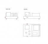
Attachments
so given a B+ of 190V and a plate swing of +/-60V you get a range of 250V to 130V.
Maybe this is an example but given the fact that E88CC should have an Ua of 120V we need a B+ of something like 130V to compensate for the RDC in the IT.
Unfortunately the IT solution does not allow the Gartner. To use coupling-caps together is somewhat surrealistic as we can skip the IT if using them😉.
Last edited:
Unfortunately the IT solution does not allow the Gartner. To use coupling-caps together is somewhat surrealistic as we can skip the IT if using them.
__________________
You are right of course, but using simple LM317 CCS's gets around that problem and allows for direct coupling. It really is an elegant solution - even though most people resist it.
The choice is - use a coupling cap, which can be chosen for it sound quality, but will always be subject to blocking distortion if driven to hard.
or use a cathode bypass cap (with bypass film cap) which has to be an electrolytic - but it is subject to 100% degenerative feedback which should eliminate most of its nastyness.
Its just about the decisions which you want to make. Personally I have built a 6080 amp with IT and it sounded great. I have built a direct coupled version and it sounded better. Given that the IT was only a cheap one comparison is not straightforward. Both had LM317 biased cathodes arranged as a differential pair at the outputs.
My 2cents worth is, if you can do it with a simple IT, then the amp becomes very elegant and simple (with no plate load CCS and no second power supply) and will definately sound top flight.
Shoog
ok, you force me to think
which is good, even if it hurts
would be nice if you would take me through the gain structure
so far, it looks like folowing, to me
input trafo/ gain of 2
driver stage/ gain of 20-25
output stage/ gain of 8 (at least thats what they say)
thats a total gain of about 30
or
I have about 30db of amplification
input trafo gives another 6db
gives a total gain of 36
its my understanding that usual average nominal standard is just about a gain of 45 to give full output
and a little less only means I can turn it up more without problems
and/or use very high sensitivity speakers
btw, I just found in 6C19* spec sheet that it runs optimal at about 100ma
with two tubes at 100ma, Broskie's supply with 100ma wont cut it
THEL in Germany makes a 500ma regulated supply
its fully adjustable, which is nice
and, at lower voltage it has another built in option for negative voltage
might be a nice option too
relatively expencive at around 200USD
on the other hand, chokes and high voltage caps cost money too
and its easy to change voltage
lots of things to think about
Hi Tinitus;
Surely you do not mean 100mA per tube? That would be for voltage regulator service,not as an amplifier. I have completed mine and it is up and running well without any tweaking except that I increased the gain of my already high gain preamp. I think you are also looking at increasing the gain of yours. I would encourage you to build the PS yourself-you can then easily fix it should anything go wrong and it is also a good "warmup" before starting the more complex wiring/layout of the amplifier itself. I always start with the PS and after testing it with a dummy load it gives me impetus to get on and finish the job. As everyone knows, it is easy to agonise over the details for a very long time and postpone actually building! You can continue to think of small design details as you are building the PS.
Surely you do not mean 100mA per tube? That would be for voltage regulator service,not as an amplifier. I have completed mine and it is up and running well without any tweaking except that I increased the gain of my already high gain preamp. I think you are also looking at increasing the gain of yours. I would encourage you to build the PS yourself-you can then easily fix it should anything go wrong and it is also a good "warmup" before starting the more complex wiring/layout of the amplifier itself. I always start with the PS and after testing it with a dummy load it gives me impetus to get on and finish the job. As everyone knows, it is easy to agonise over the details for a very long time and postpone actually building! You can continue to think of small design details as you are building the PS.
Hi Tinitus;
Surely you do not mean 100mA per tube? That would be for voltage regulator service,not as an amplifier.
I have completed mine and it is up and running well
oh
 yeah, 2x 100ma did seem strange when looking at power trafos
well, when on a new project, I am always very focused on details
so far I consider 2 options
either built a proto with the cheapest edcor trafos, and care less about the sound
or go straight at it, and build the way I want it to be
I hope it will be a winter project
 😛
😛piano3, have you shown your amp ?
btw, anyone know the Amplimo OT's ?
They have a 2.5kohm
specs say 0.5-110khz (-3db)
how is that possible ?
anyway, its cheaper than Lundahl
AE C-core are potted
AE IE-core seems almost like a bargain
Hi Tinitus,
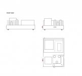
I have not yet learned how to post schematics or photos-I have only owned a computer for the last 4 years(my life has been spent playing the piano and reading books!) so my IT skills are practically nonexistant. I shall try to get my 11 yr. old niece to show me how! It might cause some amusement to see so much crammed into a small box-no noise,no hum however. I began this project as an experiment in building a differential power stage with mains toroidal OPT's. I used a scrapped case from a crazy mic amp design(too many experiments at once) and in general did not use any fancy parts,just the Soviet tubes(trioded 6E6P driver stage) and caps that I always use. Nevertheless,it clearly beats my commercial 300B in terms of transparency of sound which is rather surprising. I think you can look forward to a very good result from these 6S19P tubes. In general I do not believe in using expensive parts unless a design is tried and successfully tested-after all,you can always change to more expensive OPT's after all is working and then use the cheap ones for the next experiment.It will sound much better than you think with carefully chosen inexpensive parts. BTW, the passive power supply I described to you in words would also be quiet enough for a SE amp and it is extremely easy to build if you use a big box.
Best Regards, N.A.
from beginning of this I didnt know I would be low on drive gain
I was also looking fore a single driver triode, as opposed to double triode
reason, with SE driver I could get gain from interstage too
Revintage may be cooking on something
in the meantime why not give it a shot myself
and sorry Revintage, ecc99 😀
probably still missing parts, and issues to deal with.....same ol bias problem, eh
so far its just a thought 😱
🙂
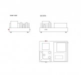
Attachments
The caps on the garter bias are wrong. As RV has said - you can't use both Garter and IT without adding caps before the grids. As it is you are averaging the bias adjustment between sides which will mess up both sides. Also you need to bypass both resistors on both sides rather than just the bottom resistor.
Shoog
Shoog
Hey Shoog and Tin,
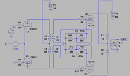
This might work to get rid of the coupling caps before the output tubes. Don´t mind the component values.
This might work to get rid of the coupling caps before the output tubes. Don´t mind the component values.
Attachments
Last edited:
Thats a really clever solution RV and I can't see why it wouldn't work.
I like the idea of keeping the LTP at the front, but only driving one input grid chucks away half of the gain (which is an issue here).
For the small extra cost I would add in an input transformer which would double the overall gain, and also possibly allow for the option of stepping up by 1:2+2. This seems like a sensible use of funds to me.
Something like this worked very well for me;
http://ly.rsdelivers.com/product/ox...2e/1122-pcb-mount-af-transformer/2106419.aspx
Because of the light loading frequency response will be better - though ringing maybe an issue. Its worth a punt as you can always upgrade it later if you find you need the extra gain. Primarys in series gives 1:1+1 primaries in parallel gives 1:2+2.
Shoog
Last edited:
- Home
- Amplifiers
- Tubes / Valves
- ecc99 - 6C19n PP, (6S19P)