Hey, I bought a bunch of 6C19N, to get started
ECC99 seem to match as driver
Should I use SE or PP driver stage
Interstage trafo could be coupled for 1:2 gain with SE to PP configuration
With PP to PP configuration only 1:1 seems possible
I could consider a line trafo, but those are expencive
Would nice with some input on this
ECC99 seem to match as driver
Should I use SE or PP driver stage
Interstage trafo could be coupled for 1:2 gain with SE to PP configuration
With PP to PP configuration only 1:1 seems possible
I could consider a line trafo, but those are expencive
Would nice with some input on this
Attachments

Don't know if this is in any way helpful, but I have a preamplifier using the ECC99. The first half of the tube is used as as common cathode amplifier with a constant current source on the anode, and the second half is a DC-connected cathode follower, again with a CCS. I get something like 56 volts peak to peak with 0.15% distortion and a bandwidth up to 450 kHz (-3dB) from a B+ around 300 volts. I think it could be optimized further, still. The amplification is around the tubes µ ~ 20.
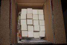
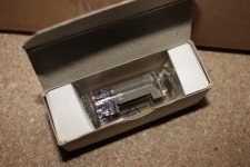
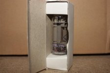
6C19N tubes
not really sure why I bought them, I just did 😛
Maybe you needed to weld something 😀
http://www.mif.pg.gda.pl/homepages/frank/sheets/113/6/6S19P.pdf
Looks like a Mu of 2 with a Rp of 600 ohms. You could drive just about anything with those things, even with a step up transformer. Mr. Miller doesn't have a chance with that low Rp.
 maybe a mix, with interstage, looks obvious to me, but is it
ahh, maybe a kind of SRPP
better forget that one
Its my understanding that adding some negative or positive bias voltage is lowering bias current, to make tube run cooler
And I dont think thats needed here
I dont know if it makes any sense to use another driver tube 😕
maybe something with biasing the second driver stage driving the IT ?
Im not sure about CCS on first driver stage B+
I read that it puts hard load on supply 😕
any opinions ?
Attachments

ahh, maybe a kind of SRPP
better forget that one
Its my understanding that adding some negative or positive bias voltage is lowering bias current, to make tube run cooler
And I dont think thats needed here
I dont know if it makes any sense to use another driver tube 😕
maybe something with biasing the second driver stage driving the IT ?
Im not sure about CCS on first driver stage B+
I read that it puts hard load on supply 😕
any opinions ?
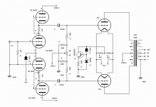
That won´t work! About #1 you must have a CCS-tail and -supply with unbalanced in. Skip #2!
Last edited:
I am building a 6S19P PP at the moment. The driver I am using has a gain of about 35 and my preamp has a very high output-more than 2 volts. ECC99 seems a little marginal in gain as the 6S19P has a mu of only 2 although you could use an input step up xformer as the phase splitter. It would be less expensive than an interstage one I would expect.If I was using a single ended preamp I would probably use a triode connected EF184 differential pair phase splitter with a constant current sink. The gain of this is about 60 and this valve is very linear triode connected.
I am building a 6S19P PP at the moment.
hey piano man, you are welcome to post your results here, or anything related
yeah, I may end up with flea power due to lack of gain
do you know what kind of power to expect from PP 6C19, with optimal gain stage ?
I am told that 6C19 is less good in SE, but much better in PP
That won´t work! About #1 you must have a CCS-tail and -supply with unbalanced in. Skip #2!
revintage, you come to my resque once again, thanks 🙂
I understand, front end as in your schematic from my previous thread with ECC99 PP
negative supply voltage is Ug(V), and curves say from -5 /-15V, depending on B+, right 🙄
Attachments
btw
Piano, I have looked at Lundahl linetrafo, as an option
LL1922 and LL1674 cost about the same as interstage
http://www.lundahl.se/pdfs/datash/1922.pdf
But I can mount it later
If this works, and not explodes 😛
😛
For now, its a matter og getting some sound, anything
and relative cheap, with Edcor OPT etc
even avarage sound would make me happy 😀 but hey, maybe Im lucky 🙂
Piano, I have looked at Lundahl linetrafo, as an option
LL1922 and LL1674 cost about the same as interstage
http://www.lundahl.se/pdfs/datash/1922.pdf
But I can mount it later
If this works, and not explodes
😛For now, its a matter og getting some sound, anything
and relative cheap, with Edcor OPT etc
even avarage sound would make me happy 😀 but hey, maybe Im lucky 🙂
1922 will probably have to low input Z for most sources. 1676 connected 1:2 will work though. If signal is lower than 2V 1544 or 1545 will also do.
About your new circuit it looks OK. But you could use fixed bias through the transformers secondary midtap. If not you could use common bypassed cathode resistor.
About your new circuit it looks OK. But you could use fixed bias through the transformers secondary midtap. If not you could use common bypassed cathode resistor.
Sorry, I can only give SE estimate quickly; If you choose an operating point of Va =190V, Ia =50mA and a 2k load, it looks like you could swing about 230V pk-pk =81V RMS which should give 3.3 watts with this load. I suppose you could count on doubling this,more or less, push-pull. With reasonably efficient speakers, this could be plenty. Or,you could use 2 pairs in parallel and half the load. If I were doing this I would compromise and use a 1.5k load for parallel operation with lower distortion.
1922 will probably have to low input Z for most sources. 1676 connected 1:2 will work though. If signal is lower than 2V 1544 or 1545 will also do.
About your new circuit it looks OK. But you could use fixed bias through the transformers secondary midtap. If not you could use common bypassed cathode resistor.
I must admit to be lost when it comes to line trafos, in general

I left out bypass cap for simpler drawing
Bias issues have been on hold until now, and time to get it sorted
Im glad you opened that issue
Hope you have time to take another look
Attachments

Go for #1, it will work fine.
thats great, thanks 🙂
maybe this one is closer to what you meant ?
bypass ?
Im not sure what you mean
I thought that a CCS would replace the cathode resistor and bypass cap
but maybe the IT is a teaser now
borrowed this EL84 bias from DHT Rob
but SE driver, and no IT
probably different
Attachments
bypass ?
Im not sure what you mean
If you bypass, you add a cap to ground over the CCS/resistor.
you must have a CCS-tail and -supply with unbalanced in.
that was very important to learn
Im still thinking about it, and it begins to make sense
and maybe Im beginning to understand how it changes available B+, steals voltage, so to speak
I suppose it means that if using input line trafo in SE to PP phase splitter configuration, then theres no need for dedicated negative bias supply
btw, bypassing ccs as you suggested, could it look like this
what kind of cap is needed
smaller film cap ok ? or supply cap electrolytic ?
I also thought about mounting grid choke like this
looks to me like kind of a phase splitter
but Im not sure it will work this way
or maybe turn it around and connect midpoint to cathodes ccs
Attachments
- Home
- Amplifiers
- Tubes / Valves
- ecc99 - 6C19n PP, (6S19P)