hey, this thread has now reached 800 views 🙂
in my book that means this thread subject goes beyond being just "my" thread, or just about "my" project
subject seems to have interest, and must be respected
lets try not to ruin it
about having this amp for a long time, I bought 20 tubes 😉
4 tubes in two monos, and playing maybe 2-3 hours a day, means they will last a long time
and I have other amps (SS)
this is just for fun, and to learn, which I already have
a year ago I knew close to nothing
I could have chosen a kit with boards
or "assembling" a proven design
but then I would still just be connecting A to B, without knowing anything about it
I really feel better prepared now
and thats what its about, to me
next move, looking at power supply
Attachments
I usually go to the Radio Lamp web site :
Ðàäèîëàìïû íà áóêâó (öèôðó) 6
and Klausmobile:
Tube List (English)
first for Soviet tubes. They has the most extensive list I've found any where (except Wavebourn, Nice data sheet!).
I considered picking up some 6C9P to use for voltage regulation till I realized that with a 140mA cathode limitation I'd need two per amp most times. Nice little Triode.
Wavebourn, if I'm below the max plate dissipation can I run the tubes with more cathode current than 140mA (say 220mA) or will the cathode starve and not be able to provide the electrons needed since the anode to plate voltage is down to 50V? Sand definatly has an advantage for voltage regulation in this regard.
Wavebourn, if I'm below the max plate dissipation can I run the tubes with more cathode current than 140mA (say 220mA) or will the cathode starve and not be able to provide the electrons needed since the anode to plate voltage is down to 50V? Sand definatly has an advantage for voltage regulation in this regard.
I don't now; I never used VR tubes for audio outputs. May be they can provide you current out of specs, but in this case I expect their lives shorter since your application will depend on their cathode emission.
May be I am wrong.
I usually go to the Radio Lamp web site :
Ðàäèîëàìïû íà áóêâó (öèôðó) 6
I considered picking up some 6C9P
I suppose you mean 6C19P 😕
according to the list you have shown its a different tube, with no grid
looks to me like its got nothing to do with 6C19C, 6C19n/II/pi, or 6S19P if you like
I think you are now considering the power supply,no? It will need to be regulated I would say as you are not using ccs to bias your pairs-and having just made 6 constant current sinks with goodness knows how many transistors I completely agree with the advice of Lars to keep it simple. Have you read the excellent series on Steve Bench's site about regulators? It is an excellent learning guide whether you intend to use tube regulation or not. You may get away without it but there is quite a big current swing.
regulated supply needs higher voltage trafo, so I need to decide
any idea how much wattage(VA) I need for B+
and I need negative voltage too
maybe I could use regulated supply on negative only, to driver
125Vac trafo should give the 190V b+
that is with no chokes
and 125Vac should be just about ok to give -125Vdc regulated
but ofcourse 220Vac trafo could be regulated to both 190Vdc B+, and the -125Vdc
http://glass-ware.stores.yahoo.net/ps2solo.html
supposedly good for 100ma
might be ok for driver stage
this is only 50ma, but might work with driver
with regulated heater as well
http://glass-ware.stores.yahoo.net/ps1kit.html
I already have two of these regulated heater supply kits
http://glass-ware.stores.yahoo.net/hps1.html
with 2.5A one each output PP channel should be just about ok
I am using a 100 VA which is pretty marginal for my design even though the supply is passive and I am wasting very little power in it which is CLCRCRC with a total resistance of only about 400 ohms. I might be inclined to build a supply for each channel in your case and use a 100VA for each channel. I am really not the person to advise you on this as I always use constant current techniques because my first projects were mic amps using differential pairs and I simply got used to this kind of thing which is so undemanding of the supply. My only concession to regulation is to often use choke input supplies. Actually, now that I think about it,if you are able to match the valves maybe it is only the driver stage which could do with regulation; you are staying in class A1,yes? You really need someone who is used to building regular push-pull amps-as Lars,for example, clearly is. Anyway,as I said, I learned a lot from Steve Bench's site even though I had/have no immediate use for this. It is very conversational, not unlike Morgan Jones's books.
I might be inclined to build a supply for each channel in your case and use a 100VA for each channel.
That was decided from day one, seperate monos 😉
100VA pr channel was my guess too, minimum
but I will need quite some heater power
Ok, I have thought a little; let us assume that you can match the tubes-maybe ask Wavebourne if he thinks this is realistic. Then try passive supply-separate heater transformer 50VA is enough for everything(unless you are going to use a tube rectifier). Wire it so that heaters come on as soon as you plug it in but B+ is switched on whenever you want. Very simple; Silicon bridge with each diode bypassed(or tube if you like!) small film cap(0.22uF) Choke 20H 150 mA,another small film cap,same value,then 470uF 450V and then the supply splits between output and driver stage. For output stage 220 ohms and 100 uF, for driver stage 470 ohms and 100 uF. This inductive filter has LF resonance of less than 2 Hz and when you get the chokes measure the DC resistance and add series resistance to make it up to 400 ohms. You should not have more than about a millivolt of ripple and I would suggest that you bypass the final electrolytics with suitable film caps of a few uF. The green Russian ones,either K75-10 or(slightly smaller) K75-24 are absolutely marvellous for this and very good value! The bypass caps should be in the amp case and not the power supply case. If you can match the valves reasonably this supply will work very well.The separate spurs for output and driver means that a regulator should not be needed and there will be little common impedance coupling between the stages(which would be degenerative anyway)
Wire it so that heaters come on as soon as you plug it in but B+ is switched on whenever you want.
good of you to mention that
actually it was my plan to use 2-gang switch to do that
maybe I could also use a softstart on B- bias to driver 😕
I need to look at your other suggestions regarding supply design
will also try and contact Broskie regarding regulated supply
will it do B- etc
and I think his supply designs needs center tapped trafo
maybe I will contact AutomaticElectricEurope on a price quote on custom trafos
If you can bare to waste a bit more voltage and want to keep it simple, Garter Bias works extremely well to keep the outputs matched.
http://www.tubecad.com/2005/May/blog0046.htm
http://www.tubecad.com/2009/04/blog0163.htm
Shoog
http://www.tubecad.com/2005/May/blog0046.htm
http://www.tubecad.com/2009/04/blog0163.htm
Shoog
Last edited:
thats need more study  😀
😀
maybe the simpler version with balance adjustment, and a balance meter, somehow
Broskie does seem to conlude that common bias resistor/cap works better than having seperate
common bias was also suggested previously by Revintage
but its my understanding that 6C19C are like factory tested quality tubes
maybe they wont be very far off
its mentioned that one reason for this balance bias scheme is problems with OPT core saturation caused by imbalance
I dont know, but with this low power, there might never be any issues with saturation
are we talking servo dc now ?
I think Revintage mentioned that, to enable use of plain toroid for OPT
😀maybe the simpler version with balance adjustment, and a balance meter, somehow
Broskie does seem to conlude that common bias resistor/cap works better than having seperate
common bias was also suggested previously by Revintage
but its my understanding that 6C19C are like factory tested quality tubes
maybe they wont be very far off
its mentioned that one reason for this balance bias scheme is problems with OPT core saturation caused by imbalance
I dont know, but with this low power, there might never be any issues with saturation
are we talking servo dc now ?
I think Revintage mentioned that, to enable use of plain toroid for OPT
Attachments
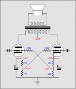
I used plain resistor garter bias on a headphone amp with toroidals as outputs. The valves were ECL82. Any imbalance much above 1mA will induce core saturation, so this scheme keeps imbalance down to that region.
As you have noted specialist OT designed for these low plate to plate loads tend to be madly expensive because of the very low demand. Surprisingly these are some of the simplest transformers to get right so cost is in no way a reflection of cost of manufacture (apart from tooling up for small production runs).
The power transformers I have used are about 35Euro and they work from about 10hz up to 50kHz in these circuits.
but its my understanding that 6C19C are like factory tested quality tubes
maybe they wont be very far off
These high current low mu tubes are very difficult to manufacture consistently so variability is likely to be high. Also since they are designed as pass regulators this is not a high design criteria anyway. If you fancy adjusting the bias every few weeks/months then thats fine. Remember as well that bias will only settle after warm up, so if you have adjusted for hot operation the amp will sound unlistenable until it comes up to temperature. Needless to say, I have never experienced the Joy of bias adjustment.
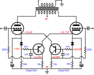
The great thing about the transistor version is that for a tiny bit more complexity you suffer no voltage/heat penalty.
Shoog
As you have noted specialist OT designed for these low plate to plate loads tend to be madly expensive because of the very low demand. Surprisingly these are some of the simplest transformers to get right so cost is in no way a reflection of cost of manufacture (apart from tooling up for small production runs).
The power transformers I have used are about 35Euro and they work from about 10hz up to 50kHz in these circuits.
but its my understanding that 6C19C are like factory tested quality tubes
maybe they wont be very far off
These high current low mu tubes are very difficult to manufacture consistently so variability is likely to be high. Also since they are designed as pass regulators this is not a high design criteria anyway. If you fancy adjusting the bias every few weeks/months then thats fine. Remember as well that bias will only settle after warm up, so if you have adjusted for hot operation the amp will sound unlistenable until it comes up to temperature. Needless to say, I have never experienced the Joy of bias adjustment.
The great thing about the transistor version is that for a tiny bit more complexity you suffer no voltage/heat penalty.
Shoog
Last edited:
on a second glance, it doesnt look so complicated
transistors are pr Broskie ordinary like MJE350
yeah, I could be tempted to give it a try 🙄
and alone checking dc out on OT would tell if it works, right
sounds almost too easy
wow, I like this
thanks Shoog
transistors are pr Broskie ordinary like MJE350
yeah, I could be tempted to give it a try 🙄
and alone checking dc out on OT would tell if it works, right
sounds almost too easy
wow, I like this
thanks Shoog
Attachments
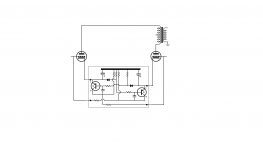
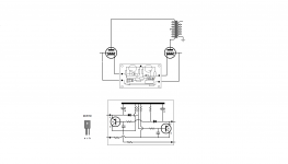

Bias
Hi Tinitus!
It seems to me, that the battery does no good, as and you are still using cathode bias in your schematic.😉
Thorsten Larsen
Hi Tinitus!
It seems to me, that the battery does no good, as and you are still using cathode bias in your schematic.😉
Thorsten Larsen
- Home
- Amplifiers
- Tubes / Valves
- ecc99 - 6C19n PP, (6S19P)