hey Thorsten
ehh, battery ?
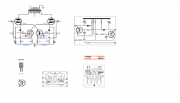
if you refer to middle schematic, its just the way Revintage shows a power supply
but you are right, it does look like the way a battery is usually shown
some will know that I enjoy drawing simpler board layout 😛 so heres a revised board layout 🙂
question is, will this advanced bias curcuit work with 6C19n(6S19P) 😕
ehh, battery ?
if you refer to middle schematic, its just the way Revintage shows a power supply
but you are right, it does look like the way a battery is usually shown
some will know that I enjoy drawing simpler board layout 😛 so heres a revised board layout 🙂
question is, will this advanced bias curcuit work with 6C19n(6S19P) 😕
Attachments

Hej Thorsten!
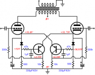
Remember this is a DC-amp. The input grids are at ca -120V, the anodes and the next stages grids at ca 0V. The output stage have ca 160V Ua. Shoog has done a working amp on this theme.
If we want to add a Gartner-circuit a DC-amp like this will not work. It will not work with an amp with IT either. So unfortunately this goes for the left amp above. To get automatic bias here a more complex servocircuit is needed. But in my opinion an automatic biascircuit will not be needed, The only thing needed is a 50ohm pot inserted between the firsts stages cathodes and the cathode resistor.
To make a cap-coupled amp no negative voltage is needed.
Last edited:
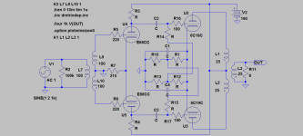
If you look at my circuit, you will see that you can get autobias if you use CCS's in the tails. This is extremely simple and I have not found any sonic penalty with this approach.
Shoog
Shoog
........ 50ohm pot inserted between the firsts stages cathodes and the cathode resistor.
To make a cap-coupled amp no negative voltage is needed.
regarding driver stage, you mean something like this, maybe
Attachments

I understand that dc from longer prolonged turn-on time of tubes could result in a severely burned amp
but I dont understand why the Blumlein Garter curcuit makes it worse
I mean, to me it still looks like ordinary auto bias with bypassed cathode resistor for biasing
but yes, it is connected to the grid
I dont know
but I dont understand why the Blumlein Garter curcuit makes it worse
I mean, to me it still looks like ordinary auto bias with bypassed cathode resistor for biasing
but yes, it is connected to the grid
I dont know
Attachments
a quote
---------------
in a directly coupled amplifier, the voltages present at the tubes are interdependent and consequently, while the tubes are heating up, the grid voltage of the output tube is wildly incorrect for a moment. The consequence is a brief period of excessively high current through the final tubes. Obviously, such abuse shortens the life of the final tube. To avoid this problem, it is necessary to delay the plate voltage until after the filaments of the tubes have reached normal operating temperature. Given that we used separate transformers to feed the filaments and for plate supply, the simplest solution is to use separate switches for the primaries of the two transformers.
---------------------------------------------------------------------------------------------------------------------------------------------------------------------------------
another quote
---------------
The purpose of a coupling capacitor is to block the voltage present on the plate of the driver tube to keep it away from the grid of the output tube. If this cap were not present, the grid of the output tube, which is referenced to ground, would be at the potential of the driver tube's plate - a couple hundred volts. This at the least would ruin the bias point of the tube, and at worst cause the tube to conduct as much current as it can get, destroying the tube and possibly a couple resistors and maybe even the rectifier. Not good. So clearly we have to do more than just remove this cap to create a direct coupled amplifier
What if the plate of the driver tube was at exactly the same voltage as the grid of the output tube? If that were true, the coupling cap would have nothing to do, and could be eliminated. That is the trick. We must find a way to raise the grid of the output tube to a voltage equal to the voltage at the plate of the driver.
In a typical RC coupled amplifier, the grid of the output tube is referenced to ground by the grid resistor. Since no current flows to or from the grid during idle, there is no voltage developed across the grid resistor and the grid is therefore at 0V. To bias the tube, the grid also must be somewhat negative in relation to the cathode. So if the grid is at 0V, we must raise the cathode up off of ground by the bias voltage, so that the grid will be at a negative voltage relative to the more-positive cathode. So we add a cathode resistor with the bias current flowing throught it to develop a voltage drop across the resistor.
----------------------------------------------------------------------------------------------------------------------------------------------------------------------------------
If we are going to tie the grid of the output tube directly to the plate of the driver tube, then we must configure the output tube so that the grid is properly biased when it is at 100V. Bias means simply that the grid is 18V less positive than the cathode. If the grid is at 100V, then all we have to do is put the cathode at 118V, and the tube will be proplerly biased. I am making this bold, because this is the "trick" to direct coupling. That is really all you have to know. So, with 25mA we can calculate the proper cathode resistor to put the cathode at 118V. R = V/I = 118V/.025A = 4720 ohms. Let's just say 4.7k.
----------------------------------------------------------------------------------------------------------------------------------------------------------------------------------
---------------
in a directly coupled amplifier, the voltages present at the tubes are interdependent and consequently, while the tubes are heating up, the grid voltage of the output tube is wildly incorrect for a moment. The consequence is a brief period of excessively high current through the final tubes. Obviously, such abuse shortens the life of the final tube. To avoid this problem, it is necessary to delay the plate voltage until after the filaments of the tubes have reached normal operating temperature. Given that we used separate transformers to feed the filaments and for plate supply, the simplest solution is to use separate switches for the primaries of the two transformers.
---------------------------------------------------------------------------------------------------------------------------------------------------------------------------------
another quote
---------------
The purpose of a coupling capacitor is to block the voltage present on the plate of the driver tube to keep it away from the grid of the output tube. If this cap were not present, the grid of the output tube, which is referenced to ground, would be at the potential of the driver tube's plate - a couple hundred volts. This at the least would ruin the bias point of the tube, and at worst cause the tube to conduct as much current as it can get, destroying the tube and possibly a couple resistors and maybe even the rectifier. Not good. So clearly we have to do more than just remove this cap to create a direct coupled amplifier
What if the plate of the driver tube was at exactly the same voltage as the grid of the output tube? If that were true, the coupling cap would have nothing to do, and could be eliminated. That is the trick. We must find a way to raise the grid of the output tube to a voltage equal to the voltage at the plate of the driver.
In a typical RC coupled amplifier, the grid of the output tube is referenced to ground by the grid resistor. Since no current flows to or from the grid during idle, there is no voltage developed across the grid resistor and the grid is therefore at 0V. To bias the tube, the grid also must be somewhat negative in relation to the cathode. So if the grid is at 0V, we must raise the cathode up off of ground by the bias voltage, so that the grid will be at a negative voltage relative to the more-positive cathode. So we add a cathode resistor with the bias current flowing throught it to develop a voltage drop across the resistor.
----------------------------------------------------------------------------------------------------------------------------------------------------------------------------------
If we are going to tie the grid of the output tube directly to the plate of the driver tube, then we must configure the output tube so that the grid is properly biased when it is at 100V. Bias means simply that the grid is 18V less positive than the cathode. If the grid is at 100V, then all we have to do is put the cathode at 118V, and the tube will be proplerly biased. I am making this bold, because this is the "trick" to direct coupling. That is really all you have to know. So, with 25mA we can calculate the proper cathode resistor to put the cathode at 118V. R = V/I = 118V/.025A = 4720 ohms. Let's just say 4.7k.
----------------------------------------------------------------------------------------------------------------------------------------------------------------------------------
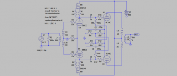
well, I can see that its obvious that the above suggested 18V/25ma cathode bias doesnt correlate well with the suggested 60V of the BroskieBlumlein curcuit
and a forced ccs doesnt seem to take care of the balanced voltage "regulation" either
also, Broskie's bias curcuit is clearly shown with series cap coupling to grid
or am I missing something
and a forced ccs doesnt seem to take care of the balanced voltage "regulation" either
also, Broskie's bias curcuit is clearly shown with series cap coupling to grid
or am I missing something
Attachments

Using a simple CCS in the tails and going direct coupled solves a number of problems. It keeps DC out of the output transformer. It compensates automatically for output tube variation. Almost as importantly - it automatically compensates for variations in driver tube plate voltage.
It achieves all of this by the simple fact that it sets its "anode" voltage to whatever it takes to achieve its set current. I have used this approach on two direct coupled amps and they work flawlessly and need no adjustment whatsoever. Two caveats are;
- the +B of the output stage needs a time delay to allow the heaters to fully come up, and for the first stage to stabalize at its operating voltage.
-the initial switch on condition can produce large voltage spikes across the CCS. I use a 125V adjustable regulator in my last amp and place a 100V zener across it to absorb these switch on spikes. Alternatively I used the IXY900 for the cathodes of my 807 direct coupled amp.
Hope that helps.
shoog
Last edited:
thanks Shoog, your input is highly valued
Revintage, your suggested schematic is of now our new reference
you never forget the smaller details, thanks
leaving direct coupled apparently also makes frontend simpler
still learning 🙂
Revintage, your suggested schematic is of now our new reference
you never forget the smaller details, thanks
leaving direct coupled apparently also makes frontend simpler
still learning 🙂
Attachments
thanks Shoog, your input is highly valued
Revintage, your suggested schematic is of now our new reference
you never forget the smaller details, thanks
leaving direct coupled apparently also makes frontend simpler
still learning 🙂
The only precaution is that 190V B+ is to low for the driver. CCS will maybe help.
thats really very very nice 🙂
I think I chose ecc99 partly for that reason
Im not too keen on paralel output tubes
Im not after higher output, or I would choose other tubes
Now that I dont need a special negative bias supply, I wouldnt mind using a seperate B+ supply for driver
If at all possible
any chance you remember the bias voltage/current on output cathode ?
edit
btw, is it significant that original "passive" BlumleinGarter you have used in sims burns more voltage and heat than the "active" Brokie version ?
as far as I understand it both curcuits try to achieve the average bias current of both tubes
The only precaution is that 190V B+ is to low for the driver. CCS will maybe help.
I think I chose ecc99 partly for that reason
Im not too keen on paralel output tubes
Im not after higher output, or I would choose other tubes
Now that I dont need a special negative bias supply, I wouldnt mind using a seperate B+ supply for driver
If at all possible
any chance you remember the bias voltage/current on output cathode ?
edit
btw, is it significant that original "passive" BlumleinGarter you have used in sims burns more voltage and heat than the "active" Brokie version ?
as far as I understand it both curcuits try to achieve the average bias current of both tubes
Member
Joined 2009
Paid Member
Out of curiosity, why is 190v too low for E88CC driver, at least I can't see this from the datasheet ?
Out of curiosity, why is 190v too low for E88CC driver, at least I can't see this from the datasheet ?
Hey Bigun,
Knowing that the sweetspot for E88CC is in the ballpark of 120V/5mA this leaves us with a very small anoderesistor giving us extremely high distortion. Also there will not be enough output level to drive the 6c... properly. If going for resistor-loading 300-400V B+ is needed.
Hey Tinitus,
ECC99 demands a little more B+, higher Ia and leaves us with to low gain. As E88CC it will also need a CCS to perform at its best. Can´t see no reason to build another expensive voltagesource when a CCS only costs a few dollars😉.

ECC99 demands a little more B+, higher Ia and leaves us with to low gain. As E88CC it will also need a CCS to perform at its best. Can´t see no reason to build another expensive voltagesource when a CCS only costs a few dollars😉.
Revintage, we now have a very nice and cost effective design, you deserve a bow

its now up to me to build it


well, its exiting 😛
if I ask you to let go of the costs considerations, what would be ideal voltages
I still like to use your CSS load of ecc88, as it seems easy and cheap to copy
and anyway, I plan to use seperate regulated supply
and preferably to each section, one for ecc88, and another for 6C19n
I see several good reasons for doing so
one is the higher voltage trafo, being fully adjustable through regulation
there are other good reasons
still, with this low power its not very costly
Member
Joined 2009
Paid Member
Hey Bigun,
Knowing that the sweetspot for E88CC is in the ballpark of 120V/5mA this leaves us with a very small anoderesistor giving us extremely high distortion. Also there will not be enough output level to drive the 6c... properly. If going for resistor-loading 300-400V B+ is needed.
Thanks for the explanation, it's all down to the basics. I guess a choke load would address this if we wanted a choke that is.
- Home
- Amplifiers
- Tubes / Valves
- ecc99 - 6C19n PP, (6S19P)