Shoog,
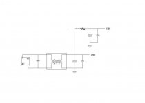
This is actually what I mailed Tin this morning. Changed it here at work in MSPaint in an attempt to make it less costly🙂.
This is actually what I mailed Tin this morning. Changed it here at work in MSPaint in an attempt to make it less costly🙂.
An externally hosted image should be here but it was not working when we last tested it.
Last edited:


Yes, that's really elegant Lars!
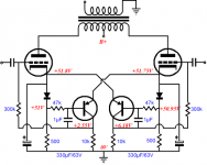
Hello Shoog, I am really amazed that the mains toroids have worked so well! I used the AC coupled cathode solution with a 3 transistor cascode in each cathode going to -17 or so volts.I got pretty lucky straight off with the matching; one pair better than 0.8% and the other about 0.2%. I may dive in later and tweak the worse of the two but for now it seems fine. My SE 300B is now retired(to emerge as something else at a later date no doubt).I am fortunate to have sensitive speakers but it worked ok with the Wharfedale Dovedale 3 that I used as a test speaker.The sound is very delicate and refined-for very little money.
Best regards,N.A.
Piano3,
Nice to hear that you can confirm my experiences on this one.
I really think that amazingly good valve amps can be built for peanuts using this methodology. None of my amps have ever cost me more than about €200.00 and they have progressively got better using exactly this technique.
Shoog
Nice to hear that you can confirm my experiences on this one.
I really think that amazingly good valve amps can be built for peanuts using this methodology. None of my amps have ever cost me more than about €200.00 and they have progressively got better using exactly this technique.
Shoog
Make certain those cathode resistors are the big heatsinked kind - and bolt them to the case away from the bypass caps. I quite often just mount the bypass caps straight from the socket pins - hanging down.
This also allows you the option of tying the caps cathodes together and having the option to try referencing them a) straight to earth b) to earth via a 1meg resistor.
Again I would be more than interested to hear other peoples impressions of the difference between bypassed and differential output pairs.
Shoog
any suggestions to OPT impedance
I was thinking something like 2.5Kohm, or anything from 1.6 - 3kohm
I was thinking something like 2.5Kohm, or anything from 1.6 - 3kohm
What current are you running through. If its at about 50mA and 200V, I would say yes something around 2.5k should do nicely.
I run my 6080's at 100V 100mA and have the transformers at 1.2K
Shoog
I run my 6080's at 100V 100mA and have the transformers at 1.2K
Shoog
Hello Shoog,
I noticed earlier that you were recommending the use of ECC91 as a driver. I have some of these that I have been trying to find a suitable use for. I wonder whether the shared cathode would impose good enough current balance to use one of our toroidals(maybe 10-20VA) as an OPT in a mic amp. It is difficult to get the gain right on a mic amp; one stage is not quite enough and two is usually too much(unless you are using ribbon mics which I do not have!). This would solve the problem as using an attenuator in a balanced amp always needs an additional CF stage and I am trying to reduce the bulk, weight and complexity of mic amps because I do not drive and must carry all my equiptment to venues usually with only one helper.
I also noticed in an earlier post of yours that you employ flourescent light chokes for preamp duty.I was wondering what size have you used and what to expect in terms of inductance/current capability. I can get the Tritonic ones locally at up to 125 watts.
Best regards, N.A.
I suggested using the ECC91 as a driver because in this context having a shared cathode is an advantage rather than a disadvantage. Used as a LTP with a CCS in the tail will help linearize this tube and side matching should be excellent, and should stay excellent for its lifetime. Gain is adequate for driving and you get to use a valve which is cheap as chips rather than the ECC88 or ECC99 family - which are rather expensive.
As to the chokes - I believe the ones I have used were in the 100W range. I have not checked the inductance as they work nicely. I have heard of them been used as plate chokes in output stages so they should be good for at least 50mA of current. I have used tiny little ones salvaged from early CFL. I am of the philosophy that a little bit of inductance in the power supply will help to filter off the line hash which comes from all the SMPS which we all have inside the house.
Shoog
Many thanks Shoog for the excellent advice. My toroid coupled 6S19P amp continues to improve each day as the valves play in-I am still astonished! It sat here half built for quite a while until you gave me the little push of encouragement. I think I could not really believe that a cheap part would work well!
Best regards, N.A.
Best regards, N.A.
Having thought about the use of Toroidals as outputs. My experiences is that they work well when they are used as step downs (as in a normal OT), but when asked to step up or do 1:1, there high interwinding capacitance comes into play and severely compromises the outputs high frequency response. As such I would say they would make poor candidates for a MIC amp.
Shoog
Shoog
But if you had too much gain, say by a factor of 4 or even 8, what then? If using ECC91 as final stage then the impedance would have to be stepped down anyway in order to interface with solid state equiptment.
I have used a toroidal as an interstage with a 1:1+1 which effectively constitutes a 1:2 step up. It was very hard to get satisfactory results.
I have also used a toroidal as an input transformer with about a 6:1+1, which is effectively a 3:1 step down. It works beautifully, with the only issue been a bit of ringing which was addressed with secondary loading with a resistor.
So my small experience says that if you can get it to 3:1 or 2:1 you will probably be fine. With the currents through the ECC91 been so low I would guess that no special precautions against DC would be needed. You should be able to get away with using a very small transformer, but in the ratios you are looking at you will probably have to settle for something around 25VA.
Something like a ECC88 for the input stage creating all the gain, and then the ECC91 LTP generating a raw voltage gain of about 30x, of which you will see just 15x (because only one input is been driven), if you then step down 4+4:1 the output stage will have a voltage gain of about 2x. Sounds very doable to me.
The +B needed is a very easy 150V which would be good for both the input and output stage. A little mains isolation transformer would do the trick, and a salvaged wallwart transformer would feed the heaters nicely. Cheap as chips all round.
Shoog
Last edited:
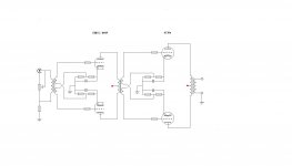
please tell me
will I get problems if using Broskie's active Blumlein bias, instead of the original passive Blumlein
Its clear there are different value resistors etc, and interstage may make it different too ?
also, any problems using Blumlein on driver stage ?
will I get problems if using Broskie's active Blumlein bias, instead of the original passive Blumlein
Its clear there are different value resistors etc, and interstage may make it different too ?
also, any problems using Blumlein on driver stage ?
Attachments

I don't see why it would be an issue.
By using the Garter on the driver you will lose a certain amount of the enforced symmetry. However by using an input tran, and an interstage symmetry should be good anyway.
Shoog
By using the Garter on the driver you will lose a certain amount of the enforced symmetry. However by using an input tran, and an interstage symmetry should be good anyway.
Shoog
I don't see why it would be an issue.
great 🙂
Im not sure why it will loose symmetry using BlumleinGarter bias on driver
I thought it would result in less dc out, thus better symmetry 😕
also, I suppose Revintage have calculated with the voltage loss from passive BlumleinGarter
maybe B+ may have to be recalculated/lowered when using Broskies active version having less voltage loss, and from that maybe also bias values 😕
and maybe I will loose the option to couple input trafo with 1:2 gain 😕
Attachments
- Home
- Amplifiers
- Tubes / Valves
- ecc99 - 6C19n PP, (6S19P)