I tried the cooking thermometer, but there’s not enough meat on the VFETs to get a good reading. Maybe I should solder on a chicken wing?
So I let it get to >90 by the IR thermometer and did the finger test. Not even 45 degrees on the Pass scale.
What gives? I tried a bunch of things to explain the apparent IR thermometer artifact:
1) the IR thermometer gives high temperature readings for only a 1 square inch region between Q2 and Q3 including part of the aluminum bracket and pcb, but not the case of Q2 or the area between Q2 and the heatsink.
2) Using masking tape or paper tape to minimize reflections does not change the reading. I turned off the lights thinking there might be a reflection, but no change.
3) The high readings ramp up quickly after turning on the power and go back to room temperature a couple of minutes after the power is turned off.
4) If I take the readings holding the IR thermometer at 3 or 6 o’clock they’re > 85, but pointing it at the same spot from 9 or 12 o’clock, the IR thermometer reads 35-40 degrees, just like the other channel.
I would love to understand why this is happening, but for the moment am happy to know smoke is not impending.
One thought: the optocoupler emits IR light. I would of thought it was contained, but perhaps the IR thermometer is picking it up?
maybe if I build a tin foil hat for the optocoupler — to match the one I wear — it will help.
maybe if I build a tin foil hat for the optocoupler — to match the one I wear — it will help.
@jamayfie,
The resistors get extremely hot, they are right next to the masking tape. Did you take a temperature reading on the other channel at the same location next to the resistors? Mine run about 85°C but are well within their max thermal limit. I’ve noticed that the laser pointer on IR temp guns is not accurate to where the temperature reading is focused on, it’s like the site on a rifle is way off, LOL!
The resistors get extremely hot, they are right next to the masking tape. Did you take a temperature reading on the other channel at the same location next to the resistors? Mine run about 85°C but are well within their max thermal limit. I’ve noticed that the laser pointer on IR temp guns is not accurate to where the temperature reading is focused on, it’s like the site on a rifle is way off, LOL!
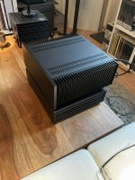
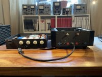
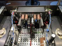
My attempt on VFet N
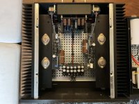
Some remarks:
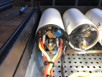
Even with really good PC-Paste and the long T-Brackets from the PP-Vfet the 120H Case (0,4 C/W) is close to the limit. 26-28°C above room temperature (measured at the heatsink).
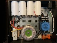
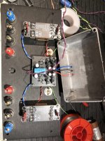
A 28V 250VA PT is also quite marginal. I get about 35,5VDC (236V in) at the VFet-PCBs in Fullwave CT-Configuration. A 30V PT would have been better. Maybe I can squezze out another 500mV with a LT4230 - PCBs arrived yesterday. Therefore the secondaries aren't twisted ;-)
As there is only one coupling cap (beside the output) upgrading from a plain Solen (which I used in the testbuild) to the Miflex 220nF was clearly a step up. In contrast to the Miflex-Upgrade which brings the most benefits in the Mid to Highs switching from a 6,8mF Panasonic HA (testbuild) to the 4,7mF Nichicon enhanced the Bass noticeable. Didn't test the 130uF path on speakers yet but with headphone it sounds really fine.
Verdict: this is a ridiculous good sounding amp - thanks Nelson! The only downside: I would like to have about 5 Watts more - maybe i find a semi-matched pair of sk180 some day.
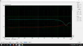
I'm not 100% sure about my distortion measurements cause I have not much experience with ARTA/STEPS but they are in the area of Nelsons measurements of the VFet P. The higher distortions in the upper region comes from the 1:11,6 connection. In 1:5,8 the distortions are higher in bass but lower in highs. Also you have to use an output resistor with the LL1930 to tame the heavy peak at 40-50kHz - I went for 10R but if I had one at home I would have used 22R. 33R is a tad too much -1dB at 20kHz.
- Frontend Dual DCB1 (1R Deg) - so no coupling caps at In- or Output
- Interstage LL1930 1:11,6
- no Zobel on secoundaries (raises Distortion)
- ext. PS CLC 88mF 10mH VFet & Supply +/- 16V (due to space limitations)
- 2x 6mF decoupling in amp chassis
- bipolar L-Adapter for FE
- 2 Outputs 4,7mF or 130uF DC-Link (tweeter/HP)
- simple relay circuit based on IRF510 (DCB1 & Output caps)
- Mini-Disspipante 120H x 300D
- I used almost only parts that I have at home (except case & 250VA PT)
Some remarks:
Even with really good PC-Paste and the long T-Brackets from the PP-Vfet the 120H Case (0,4 C/W) is close to the limit. 26-28°C above room temperature (measured at the heatsink).
A 28V 250VA PT is also quite marginal. I get about 35,5VDC (236V in) at the VFet-PCBs in Fullwave CT-Configuration. A 30V PT would have been better. Maybe I can squezze out another 500mV with a LT4230 - PCBs arrived yesterday. Therefore the secondaries aren't twisted ;-)
As there is only one coupling cap (beside the output) upgrading from a plain Solen (which I used in the testbuild) to the Miflex 220nF was clearly a step up. In contrast to the Miflex-Upgrade which brings the most benefits in the Mid to Highs switching from a 6,8mF Panasonic HA (testbuild) to the 4,7mF Nichicon enhanced the Bass noticeable. Didn't test the 130uF path on speakers yet but with headphone it sounds really fine.
Verdict: this is a ridiculous good sounding amp - thanks Nelson! The only downside: I would like to have about 5 Watts more - maybe i find a semi-matched pair of sk180 some day.
I'm not 100% sure about my distortion measurements cause I have not much experience with ARTA/STEPS but they are in the area of Nelsons measurements of the VFet P. The higher distortions in the upper region comes from the 1:11,6 connection. In 1:5,8 the distortions are higher in bass but lower in highs. Also you have to use an output resistor with the LL1930 to tame the heavy peak at 40-50kHz - I went for 10R but if I had one at home I would have used 22R. 33R is a tad too much -1dB at 20kHz.
Attachments
-
 1.jpg482.5 KB · Views: 231
 -
 2.jpg495.9 KB · Views: 251
 -
 3.jpg509.8 KB · Views: 248
 -
 4.jpg446 KB · Views: 261
 -
 5.jpg688 KB · Views: 244
 -
 6.jpg621.5 KB · Views: 231
 -
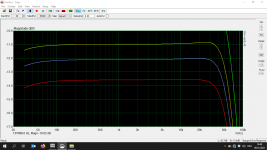 FR 1Watt 4 vs 6 vs 8Ohm.png22.5 KB · Views: 212
 -
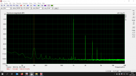 Spectrum 1Watt 4Ohm.png25.4 KB · Views: 197
 -
 Distortion 1Watt 4Ohm.png19.6 KB · Views: 202
 -
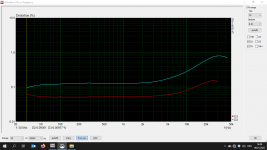 Distortion 1Watt 8Ohm.png19.5 KB · Views: 191

Wow, really nice work Galac!!
The LT4320 active rectifier should net you almost another volt and reduce psu chassis temps. (You can’t use a CT transformer configuration with it though)
Enjoy!

The LT4320 active rectifier should net you almost another volt and reduce psu chassis temps. (You can’t use a CT transformer configuration with it though)
Enjoy!
Clearly a very meticulous build executed toward a specific vision. All I can offer are a couple ideas:
1) The heatsinks used in the store version of the VFET amp are the same size and hole pattern as the 4U x 300mm Deluxe chassis. Larger and capable of dissipating more energy.
2) A pair of 160VA power transformers, one for each channel, will exhibit less voltage drop and better regulation than a single 250VA. The 28V secondaries are enough for a CLC filter. A pair of 15V secondaries in series (total 30V) work well for a CapMx style supply such as the SLB.
Thanks all for your kind feedback!
This evening I tried the separate 130uF tweeter path. I suspected that it maybe will introduce some unbalance to the sound. But no - a huge step up. More PRAT and transparency with getting fatigued. Even bad recordings are still listenable. If I ever want to upgrade this amp the first step would be a DC-Link cap in parallel to the 4,7mF output electrolytic or more likely a direct input rca to test some tube FE 😉
This evening I tried the separate 130uF tweeter path. I suspected that it maybe will introduce some unbalance to the sound. But no - a huge step up. More PRAT and transparency with getting fatigued. Even bad recordings are still listenable. If I ever want to upgrade this amp the first step would be a DC-Link cap in parallel to the 4,7mF output electrolytic or more likely a direct input rca to test some tube FE 😉
Number 091 is built, tested and playing in my office test system! Thanks to Nelson and the DIYAudio team for a fantastic amplifier.

She much prefers this 10W class A amp to the 50W class D it replaced, although a 500W space heater is still her favorite. A pair of Tonkin mono blocks may be a good compromise in the future. In the mean time, my “test” speakers (Gallo micro nucleus) have no business sounding this good.The dog obviously approves!

Hi.
I am sure the question was alredy in this thread somewhere, but how can I eliminate or minimize the POP when powering down the sweet amp?
On my JBL4345 there is sometimes a very loud POP.
Thank you for your help!
regards
I am sure the question was alredy in this thread somewhere, but how can I eliminate or minimize the POP when powering down the sweet amp?
On my JBL4345 there is sometimes a very loud POP.
Thank you for your help!
regards
Member Mark Johnson has written about the turn off thump:i know but it makes me feel better with my 2405 and 2420...
https://www.diyaudio.com/community/...2-n-channel-build.375437/page-28#post-6789777
and designed a circuit to minimize it:
https://www.diyaudio.com/community/threads/diy-sony-vfet-pt-2-n-channel-build.375437/post-6776029
Builders of the circuit reported good results:
https://www.diyaudio.com/community/threads/diy-sony-vfet-pt-2-n-channel-build.375437/post-6783871
I’m currently using the DPDT circuit in the article instead of the single pole switch included in the kit, but have considerable turn on and turn off thumps on my insensitive speakers. I haven’t bothered to address them.
- Home
- Amplifiers
- Pass Labs
- DIY Sony VFET pt 2 (N-Channel Build)